Friction tongue lock body reversing structure

A technology of tongue lock and lock housing, applied in the field of reversing structure of friction tongue lock body, which can solve the problems of poor lock applicability, inability to reversing, not so beautiful, etc., to achieve reasonable structure, convenient reversing adjustment, and ensure the force The effect of strength and aesthetics

Active Publication Date: 2014-01-29
ZHONG SHAN OLANG METAL PROD CO LTD
View PDF8 Cites 2 Cited by
  • Summary
  • Abstract
  • Description
  • Claims
  • Application Information

AI Technical Summary

Problems solved by technology

[0003] One is that the lock of the left-handed or right-handed door is directly determined when leaving the factory, and it cannot be reversed. When it is suitable, it needs to be taken back and replaced. This kind of lock has poor applicability;
[0004] One is to open a large reversing gap on the bottom plate and cover plate of the lock case. When reversing is required, retract the friction tongue and the friction tongue trigger tongue together to the gap of the lock case, and then turn it over 180 degrees. To change the direction, although this kind of lock can be changed by the user himself, the big gap will make the whole lock look less beautiful, and will also reduce the force strength of the lock case;
[0005] There is also a way to change direction by removing the side panel, which is very inconvenient to operate for non-professional users

Method used


Image

  • Friction tongue lock body reversing structure
  • Friction tongue lock body reversing structure
  • Friction tongue lock body reversing structure

Examples


Embodiment Construction

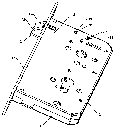
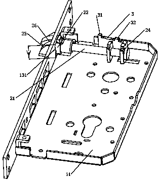
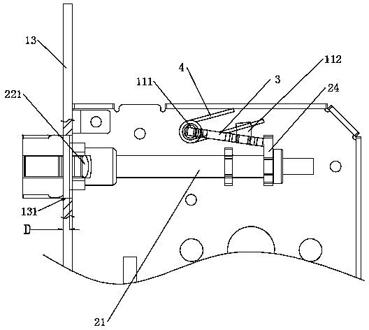
[0018] The present invention is a reversing structure of friction tongue lock body, such as Figure 1 to 3 As shown, it includes a lock housing 1 composed of a bottom plate 11, a cover plate 12, and a side plate 13, and a friction tongue assembly 2 installed in the lock housing 1. The friction tongue assembly 2 includes friction tongue rods 21, which are respectively installed The circular friction tongue seat 22, the friction tongue spring (not shown in the figure) and the friction tongue toggle block 24 on the three front, middle and rear parts of the friction tongue rod 21 are installed on the upper and lower two parts of the friction tongue seat 22. A friction tongue 25 and a friction tongue touch tongue 26 oscillatingly connected between the two friction tongues 25. These structures are basically the same as the current lock body with friction tongues. The difference is: There is a reversing control board 3 and a spring 4 that makes the reversing control board 3 always swi...


PUM


Abstract

Provided is a friction tongue lock body reversing structure. An oblique plane is formed on the surface, opposite to a touching tongue of a friction tongue, of a friction tongue base. The displacement of a left vertical edge of a boss when the supporting driving boss of the touching tongue of the friction tongue swings from a position making contact with a side plate to a position where the boss leans on the oblique plane is larger than the distance that the tail end of the friction tongue is hidden into the side plate before reversing of a reversing control plate is relieved. Accordingly, after the limitation on a shifting block by the reversing control plate is relieved, and when the touching tongue of the friction tongue swings backwards to lean on the oblique plane of the friction tongue base under the action of a friction tongue spring, the whole friction tongue slides out of a friction tongue slide hole of the side plate, and therefore the reversing of the whole friction tongue assembly can be achieved in a manner than the friction tongue rotates by 180 degrees in the friction tongue slide hole of the side plate when the friction tongue assembly rotates in a bottom plate horizontally. Big reversing notches do not need to be formed in the bottom plate and a cover plate, and the trouble that the side plate needs to be disassembled to achieve reversing is avoided. Therefore, the friction tongue lock body reversing structure is reasonable in structure and can ensure the stress strength and beauty of a lock shell, and the reversing adjustment is convenient.

Description

【Technical Field】 [0001] The invention relates to a lock body with friction tongues such as anti-theft locks and armored locks, in particular to the friction tongue reversing structure of these lock bodies. 【Background technique】 [0002] We know that armored locks, anti-theft locks and other lock bodies with friction tongues are often suitable for left-opening or right-opening doors. In order to make the locks produced can be installed on the left-opening door or on the right-hand door. On the door of the door, these locks are often provided with a reversing structure. The current lock body structure has the following three methods: [0003] One is that the left-opening or right-opening lock is directly determined at the factory. It cannot be reversed. That is to say, the user must know whether his door is left-opening or right-opening when buying, otherwise he won’t buy it back. You have to take it back and change when appropriate, this kind of lock has poor applicability; [000...

Claims


Application Information

Patent Timeline
Patent Type & Authority Applications(China)
IPC IPC(8): E05B15/10
Inventor 胡利恒
Owner ZHONG SHAN OLANG METAL PROD CO LTD
Why Eureka
Try Eureka