Eureka AIR delivers breakthrough ideas for toughest innovation challenges, trusted by R&D personnel around the world.

A multifunctional coal mining hydraulic protection arm raking support device

A support device and multi-functional technology, which is applied in mine roof support, mining equipment, earth square drilling, etc., can solve the problems of high labor intensity, large number of people, and low production efficiency, so as to improve safety and occupational health, reduce The number of personnel and the effect of improving production efficiency

Active Publication Date: 2016-11-30
BEIJING CHENGTIAN HENGYE COAL MINE EQUIP CO LTD
View PDF8 Cites 0 Cited by
  • Summary
  • Abstract
  • Description
  • Claims
  • Application Information

AI Technical Summary

Problems solved by technology

[0005] A coal shearer disclosed above still has the following defects: the total weight of the equipment is large, and there are many links, so the cost is also very high
[0007] The above-mentioned new blasting coal mining technology for coal mining face still has the following defects: because there is no base, the stability of the support is poor, and because there is no connection mechanism with the conveyor, it is inconvenient to push the conveyor
Not only that, after the blasting, because a large amount of falling coal enters the space of the bracket, the workload of cleaning the blasted coal in the bracket is very heavy, and the parts of the bracket are also easily damaged by the blasting, which affects the normal production and repetitive work. The large quantity and the slow speed of moving the support, these problems that are difficult to customer service together constitute a fundamental reason for the low production efficiency of the blast mining process
Especially in the coal loading process, the blasting coal is completely loaded into the conveyor with a shovel manually, the production efficiency is extremely low, the labor intensity of the workers is very high, and there are many people employed. At the same time, the production working environment is relatively harsh

Method used


Image

  • A multifunctional coal mining hydraulic protection arm raking support device

Examples


Embodiment Construction

[0023] The preferred embodiments of the present invention will be described below in conjunction with the accompanying drawings. It should be understood that the preferred embodiments described here are only used to illustrate and explain the present invention, and are not intended to limit the present invention.

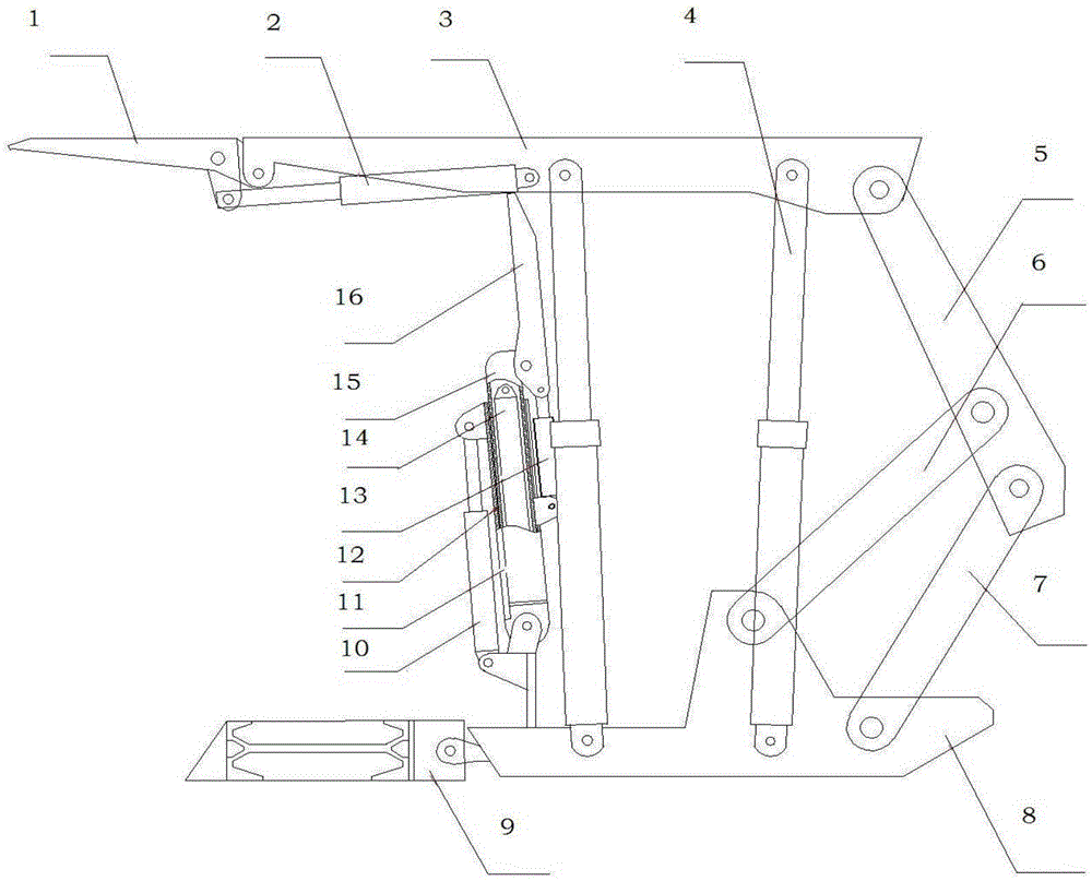
[0024] As shown in the figure, a schematic structural diagram of a multi-functional coal mining hydraulic protection arm raking support device, including an overturning cover beam 1, an overturning cover beam jack 2, a top beam 3, a hydraulic column 4, a cover beam 5, a front connecting rod 6, Rear connecting rod 7, base 8, scraper conveyor 9, protective arm support jack 10, energy-absorbing protective plate 11, protective arm 12, rake coal hopper jack 13, telescopic arm jack 14, telescopic arm 15, rake coal hopper 16 .

[0025] A multi-functional coal mining hydraulic protection arm raking support device, the raking support device not only has the protective functi...


PUM


Abstract

The present invention relates to a raking support device for a multi-functional coal mining hydraulic protective arm. The device includes: an overturning cover beam, an overturning cover beam jack, a top beam, a hydraulic column, a cover beam, a front connecting rod, a rear connecting rod, a base, Scraper conveyor, protective arm support jack, energy-absorbing protective plate, protective arm, rake coal hopper jack, telescopic arm jack, telescopic arm, rake coal hopper, the flip cover beam is connected with the flip cover beam jack, the flip The cover beam, the overturn cover beam jack, the hydraulic column, and the cover beam are respectively connected with the top beam, the cover beam is connected with the front link and the rear link, and the hydraulic column, scraper conveyor, front link, rear link and The base is connected, the telescopic arm jack is connected with the telescopic arm, the protective arm support jack is connected with the protective arm, the protective arm is connected with the energy-absorbing protective plate, and the protective arm is arranged on the multifunctional coal mining hydraulic protective arm. Rake mount bracket unit front.

Description

technical field [0001] The invention relates to a coal mining device, in particular to a multifunctional coal mining hydraulic protection arm raking support device. Background technique [0002] At present, the production technology adopted by underground coal mines at home and abroad is basically divided into two categories: one is the use of coal shearer, which is responsible for spiral cutting and coal loading, scraper conveyor is responsible for coal transportation and hydraulic support is responsible for support. Roof protection, that is, three-machine supporting combined coal mining, this production process is referred to as machine mining. The advantages of the machine mining process are: high production efficiency and good safety performance. [0003] Another production process is to mine coal by blasting and dropping coal, which is called blast mining for short. The advantage of blast mining technology over mechanical mining technology is that it has lower require...

Claims


Application Information

Patent Timeline
Patent Type & Authority Patents(China)
IPC IPC(8): E21D23/03E21D23/04E21D23/16
Inventor 王洪英徐兴强陈志才陈汉章舒文利王昱石洪起
Owner BEIJING CHENGTIAN HENGYE COAL MINE EQUIP CO LTD
Why Eureka
Eureka Blog
Learn More