Lubricating device for supplying a tool with lubricant

A lubricating device and lubricant technology, applied in the direction of engine lubrication, distribution device, lubricating parts, etc., can solve problems such as tool damage, and achieve the effect of preventing damage

Inactive Publication Date: 2014-01-29
SMS MEER
View PDF7 Cites 10 Cited by
  • Summary
  • Abstract
  • Description
  • Claims
  • Application Information

AI Technical Summary

Problems solved by technology

There is therefore a huge risk of tool damage if insufficient functionality of the lubrication system is not recognized in time

Method used


Image

  • Lubricating device for supplying a tool with lubricant
  • Lubricating device for supplying a tool with lubricant

Examples


Embodiment Construction

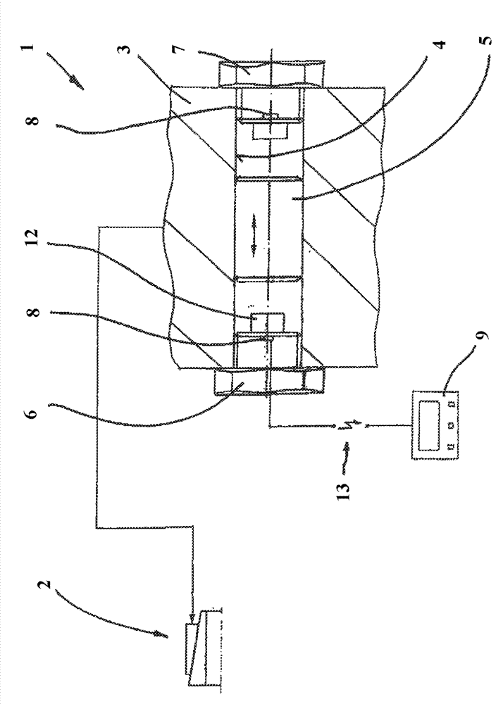
[0035] exist figure 1 A lubricating device 1 for supplying a tool 2 with a lubricating substance is shown. Tool 2 is a tube expansion tool, for example the tool described in document DE 100 08 688 C1.

[0036] The core component of the lubricating device 1 is the lubricating distributor 3, the general construction of which is known as such. The lubricating distributor 3 therefore has a piston bore 4 in order for the piston 5 to be able to move back and forth in the bore 4; this is achieved by figure 1 indicated by the double arrows in . The piston bore 4 is blocked at its end, and the blocking bolts 6 and 7 are used for this purpose.

[0037] The blocking screws 6 and 7 are also used for metering the precise lubricant volume, since for this purpose the axial mobility of the piston 5 and thus the volume of lubricant applied per piston stroke is also limited.

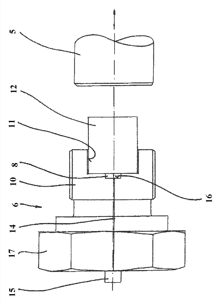
[0038] What is important and new is that a sensor 8 is arranged on each of the two locking bolts 6 and 7 . These t...


PUM


Abstract

The invention relates to a lubricating device (1) supplying lubricating agents, especially lubricating grease or lubricating oil to a tool (2). The lubricating device (1) comprises a lubricating distributor (3). At least one piston hole (4) is introduced into the lubricating distributor. A piston (5) which can move back and forth is arranged inside the piston hole. The piston hole (4) parts in the axial end part areas can be locked respectively through locking bolts (6, 7). In order to guarantee the monitoring of a lubricating system especially when used in a pipe expanding tool, the invention has at least one sensor (8) arranged in or beside at least one locking bolt (6). The sensor is connected with a monitoring device (9) so as to detect and monitor at least one running parameter of the lubricating distributor (3).

Description

technical field [0001] The invention relates to a lubricating device for supplying tools with lubricant, in particular lubricating oil or grease, wherein the lubricating device comprises a lubricating distributor into which at least one piston bore is introduced, in which it can move back and forth. Pistons are arranged, wherein the piston bores are each blocked in their axial end regions by means of blocking screws. Background technique [0002] In order to function properly, different types of tools must be supplied with lubricant, wherein in particular oil or grease must be supplied in sufficient quantities. Mention is made by way of example, but also as an embodiment of particular importance in this context, of a tube dilation tool, as described, for example, in DE 100 08 688 C1. [0003] For supplying such tools, lubricating devices of the type mentioned at the outset are known, which have a lubricating distributor. In most cases, a plurality of bores are incorporated...

Claims


Application Information

Patent Timeline
Patent Type & Authority Applications(China)
IPC IPC(8): F16N23/00F16N29/00B21D39/20
CPCF16N2250/08F16N2250/04F16N25/02
Inventor M.托皮特H.奥伯维兰S.施托伊尔曼A.托皮特
Owner SMS MEER
Why Eureka
Try Eureka