Noise reduction device of refrigerant separator

A separator and refrigerant technology, which is applied in the direction of refrigerators, refrigeration components, refrigeration and liquefaction, etc., can solve the problems of high noise of the gas-liquid separator and affect the comfort of the environment, and achieve reduced operating noise, strong practicability, and prevention of The effect of corrosion

Inactive Publication Date: 2014-01-29
郭斌
8 Cites 0 Cited by

AI-Extracted Technical Summary

Problems solved by technology

The noise of the existing gas-liquid separator is relati...

Abstract

The invention discloses a noise reduction device of a refrigerant separator. The noise reduction device of the refrigerant separator comprises a cylindrical noise reduction main body, wherein a pair of locking through holes is formed in the sidewall of the noise reduction main body, and a locking slot is formed in the bottom of the sidewall of the noise reduction main body. With the utilization of the noise reduction main body which is made of tripolycyanamide foam, the noise reduction device of the refrigerant separator, on one hand, is able to absorb harmful vibration of the separator and reduces running noise of the separator greatly, and on the other hand, is able to absorb leaked refrigerant on the surface of the separator efficiently to prevent refrigerant from corroding a surface coating of the separator, prolongs the service life of the separator and achieves strong practicability.

Application Domain

Technology Topic

Melamine foamEngineering +2

Image

  • Noise reduction device of refrigerant separator
  • Noise reduction device of refrigerant separator

Examples

  • Experimental program(1)

Example Embodiment

[0015] The preferred embodiments of the present invention will be described in detail below in conjunction with the accompanying drawings, so that the advantages and features of the present invention can be more easily understood by those skilled in the art, and the protection scope of the present invention will be defined more clearly.
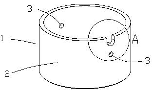
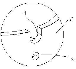
[0016] Such as Figure 1 to Figure 2 As shown, the noise reduction device 1 of the refrigerant separator of the present invention includes a cylindrical noise reduction body 2, and a pair of locking through holes 3 are provided on the side wall of the noise reduction body 2. A locking notch 4 is provided at the bottom of the side wall.
[0017] The noise reduction body 2 is made of melamine foam.
[0018] The outer side wall of the noise reduction main body 2 is provided with a silica gel layer.
[0019] The above are only specific implementations of the present invention, but the protection scope of the present invention is not limited thereto. Any changes or replacements that are not thought of through creative work shall be covered by the protection scope of the present invention. Therefore, the protection scope of the present invention should be subject to the protection scope defined by the claims.

PUM

no PUM

Description & Claims & Application Information

We can also present the details of the Description, Claims and Application information to help users get a comprehensive understanding of the technical details of the patent, such as background art, summary of invention, brief description of drawings, description of embodiments, and other original content. On the other hand, users can also determine the specific scope of protection of the technology through the list of claims; as well as understand the changes in the life cycle of the technology with the presentation of the patent timeline. Login to view more.

Similar technology patents

Classification and recommendation of technical efficacy words

  • Avoid corrosion
  • Reduce running noise

Tree pole coupler system

InactiveUS20100072747A1Easily insertAvoid corrosionSleeve/socket jointsArtificial flowers and garlandsConcentric cylinderTree trunk
Owner:THE PRE LIT TREE CONCEPT

Conductive plastic drain board

ActiveCN102720182AConductive CorrosionAvoid corrosionSoil preservationElectrically conductiveMetallic electrode
Owner:WUHAN UNIV +1

Engine coolant

ActiveCN101768428AAvoid corrosionGood corrosion inhibitionHeat-exchange elementsIonAutomotive engineering
Owner:北京蓝星清洗有限公司

Air channel structure and air conditioner

InactiveCN105546777AGuaranteed heat exchange and heat exchange effectReduce running noiseDucting arrangementsLighting and heating apparatusAerospace engineeringAir channel
Owner:GREE ELECTRIC APPLIANCES INC
Why Eureka
Try Eureka