Method and device for magnetic powder inspection on annular workpiece

A technology of magnetic particle inspection and annular workpiece, applied in the direction of material magnetic variables, etc., can solve the problems of affecting inspection accuracy, time-consuming and labor-intensive, low work efficiency, etc., to improve the efficiency of magnetic particle inspection and prevent sensitivity interference and power loss.

Active Publication Date: 2014-01-29
厉伟
View PDF7 Cites 3 Cited by
  • Summary
  • Abstract
  • Description
  • Claims
  • Application Information

AI Technical Summary

Problems solved by technology

[0010] Using this method for magnetic particle flaw detection of ring-shaped workpieces has the following unavoidable disadvantages: 1. There are blind spots in flaw detection. In this method, the workpiece is placed vertically. The holding surface will cause a blind area in the flaw detection process, and there may be missed inspections for defective workpieces. In addition, the holding surface will also cause poor magnetization effect on the surface of the component, which will affect the accuracy of flaw detection.
2. The work efficiency is low. Each workpiece can only be carried out in one step from the beginning of material loading to magnetization flaw detection, observation, demagnetization and other operations. The workpieces can only be inspected one by one, which is time-consuming and labor-intensive. It is not suitable for large-scale industrial production. Requirements for rapid detection of batch workpieces

Method used


Image

  • Method and device for magnetic powder inspection on annular workpiece
  • Method and device for magnetic powder inspection on annular workpiece
  • Method and device for magnetic powder inspection on annular workpiece

Examples


Embodiment Construction

[0037] The technical solutions of the present invention will be described in detail below in conjunction with specific embodiments. Herein, the exemplary embodiments and descriptions of the present invention are used to explain the technical solutions of the present invention, but are not intended to limit the present invention.

[0038] This example:

[0039] This embodiment provides a method for magnetic particle flaw detection of an annular workpiece, comprising the following steps:

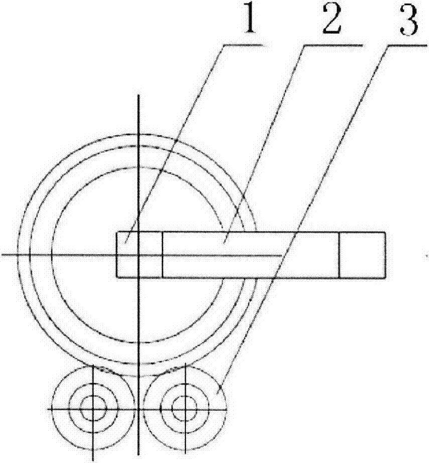
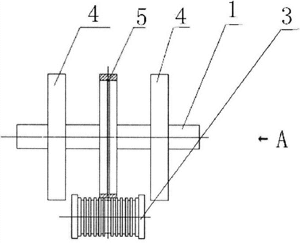
[0040] Step 1: Set the workpiece model and diameter parameters through the host computer software, and the equipment automatically controls the feeding alignment device to ensure that the workpiece is aligned with the center in the horizontal direction of the pallet;

[0041] Step 2: Place the workpiece on the workpiece bracket at the loading level through a loading device such as a row crane (or cantilever crane) to achieve horizontal center alignment;

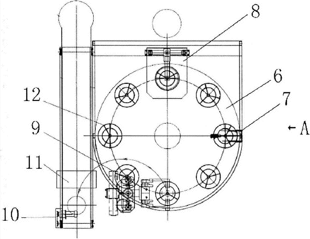
[0042] Step 3: The 8-station step-by-...


PUM


Abstract

The invention relates to the technical field of magnetic powder inspection and discloses a method and a device for magnetic powder inspection on an annular workpiece. 8-station flow process layout is adopted so that the whole inspection process frequency only depends on magnetic powder inspection observation time and thus magnetic powder inspection efficiency is maximumly improved and magnetic powder inspection requirements on various batch annular workpieces are satisfied. An annular workpiece is horizontally and firmly placed on a workpiece tray without an assistant clamping device, the workpiece tray is provided with three strip peak-shaped support frames which are arranged in angle of 120 degrees, the end surface of the bottom of the annular workpiece contacts with only three peak lines of the support frames so that a dead zone caused by a support surface is maximumly avoided, and the annular chassis of the workpiece tray is provided with an open structure so that the interference produced by a ring induced current on detection sensitivity and an electric energy loss are effectively prevented.

Description

technical field [0001] The invention relates to the technical field of magnetic particle flaw detection, in particular to a method and a device for magnetic particle flaw detection of an annular workpiece. Background technique [0002] At present, the circumferential rod-piercing method (central conductor method) and the longitudinal yoke induction method are mostly used for flaw detection of inner parts of bearing rings. The method of magnetic particle inspection according to figure 1 As shown, the inspected annular workpiece is vertically placed on two rotating rollers, and the central conductor rod passes through the center hole of the inspected annular workpiece. The specific operation steps are as follows: [0003] 1) Place the workpiece on the rotating roller through a loading device such as a row crane (or cantilever crane); [0004] 2) Manually observe whether the height of the workpiece is suitable for the central conductor magnetic rod to pass through, and the op...

Claims


Application Information

Patent Timeline
IPC IPC(8): G01N27/84
Inventor 厉俱德
Owner 厉伟
Why Eureka
Try Eureka