Manufacturing method of test block having surface artificial crack defect used for magnetic particle testing

An artificial crack and magnetic particle detection technology, applied in the preparation of test samples, material magnetic variables, etc., can solve the problems of poor controllability of crack direction, irregular crack defects, and difficult to determine the specific position of crack defects, etc., to achieve crack direction Controllable, good forming quality, realistic effect of crack defects

Inactive Publication Date: 2016-02-24
HEFEI UNIV OF TECH +1
View PDF6 Cites 11 Cited by
  • Summary
  • Abstract
  • Description
  • Claims
  • Application Information

AI Technical Summary

Problems solved by technology

However, the crack defects produced by this invention patent are irregular, and the controllability of the cra

Method used


Image

  • Manufacturing method of test block having surface artificial crack defect used for magnetic particle testing
  • Manufacturing method of test block having surface artificial crack defect used for magnetic particle testing
  • Manufacturing method of test block having surface artificial crack defect used for magnetic particle testing

Examples


Embodiment 1

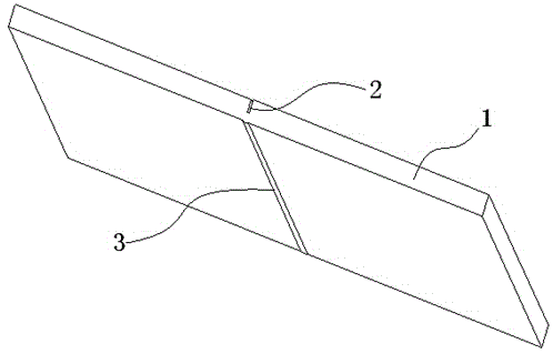
[0025] ① Use a sawing machine to process a saw groove with a depth of 6mm and a width of 1.2mm on the upper surface of the base material Q245R test block with a specification of 300mm×300mm×12mm;

[0026] ②Welding a layer of weld I with a thickness of 2~3mm on the lower surface of the test block directly opposite the saw groove, such as figure 1 Shown

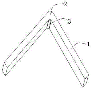
[0027] ③Before the test block is cooled, immediately use the weld Ⅰ as the central axis to mechanically make the test block bend, such as figure 2 As shown (the welding seam is outside the inner saw groove), after the cracks appear at the bottom of the saw groove, restore the test block to a horizontal shape;

[0028] ④ Process the saw groove into a U-shaped groove with a depth of 5mm and a width of 8mm;

[0029] ⑤ Fill the U-shaped groove in three layers of welding. The welding parameters of the first layer are J422Φ3.2 type electrode, the welding current is 130A, the voltage is 24±2V, and the welding speed is 15mm / min; the welding pa...

Embodiment 2

[0033] ① Use a sawing machine to process a saw groove with a depth of 8mm and a width of 1.2mm on the upper surface of the Q245R test block with a specification of 300mm×300mm×12mm;

[0034] ②Welding a layer of weld with a thickness of 2~3mm on the lower surface of the test block facing the saw groove Ⅰ;

[0035] ③ Immediately before the test block is cooled, use the weld as the central axis to mechanically bend the test block. After the cracks appear at the bottom of the saw groove, restore the test block to a horizontal shape;

[0036] ④ Process the saw groove into a U-shaped groove with a depth of 7mm and a width of 7mm;

[0037] ⑤ Fill the U-shaped groove in three layers of welding. The welding parameters of the first layer are J422Φ3.2 type electrode, the welding current is 130A, the voltage is 24±2V, the welding speed is 15mm / min, and the welding parameters used for the second and third layers It is: J422Φ3.2 electrode, welding current 170A, voltage 24±2V, welding speed 10mm / min...


PUM


Abstract

The invention discloses a manufacturing method of a test block having surface artificial crack defect used for magnetic particle testing. The manufacturing method includes processing a sawing groove on the test block with a sawing machine, welding a weld joint on the test block directly beneath the sawing groove; bending the test block to cause a crack with the weld joint as a center line, restoring the test block to be horizontal; processing the sawing groove to be a U-shaped bevel; welding and filling the U-shaped bevel; polishing the weld joint to flush with a base material, rewelding the weld joint; and polishing again the weld joint to flush with the base material test block. The manufacturing method can manufacture the test block having surface artificial crack defect rapidly, is suitable for magnetic particle nondestructive testing method, and has important meaning in training the magnetic particle inspection personnel, testing and researching the flaw detection material property, and improving the understanding of the magnetic particle detection signal. The prepared surface crack of the test block is different with the artificial defect of a flaw detection standard test block, and the crack defect is real and easily available.

Description

technical field [0001] The invention relates to a crack defect test block, in particular to a method for making a surface artificial crack defect test block for magnetic particle detection. Background technique [0002] In recent years, non-destructive testing technology has achieved unprecedented development. As an effective method to evaluate internal or external surface defects without destroying the object to be tested, scientific and technological workers are researching and realizing quality control, process improvement, and improving equipment performance. A lot of work has been done. In order to find out whether a certain non-destructive testing system can work in the expected way and with the required sensitivity, the most direct way is to assess the ability of the system to detect known defects, and the most ideal way is to make a batch of uniform natural cracks Test blocks, but the differences in the production methods of each unit lead to differences in qualit...

Claims


Application Information

Patent Timeline
IPC IPC(8): G01N27/84G01N1/28
CPCG01N1/28G01N27/84
Inventor 吴玉程洪勇舒霞史红兵张俊斌
Owner HEFEI UNIV OF TECH
Why Eureka
Try Eureka