Imaging system for patterning of an image definition material by electro-wetting and methods therefor

An image-defining technology, applied to the equipment of the electric recording process using the charge pattern, the electric recording process using the charge pattern, the electric recording process using the charge pattern, etc.

Active Publication Date: 2014-01-29
PALO ALTO RES CENT INC
View PDF9 Cites 9 Cited by
  • Summary
  • Abstract
  • Description
  • Claims
  • Application Information

AI Technical Summary

Problems solved by technology

[0016] Accordingly, the present disclosure addresses the above problems and others, enabling the printing of variable content without complex toner and support systems

Method used


Image

  • Imaging system for patterning of an image definition material by electro-wetting and methods therefor
  • Imaging system for patterning of an image definition material by electro-wetting and methods therefor
  • Imaging system for patterning of an image definition material by electro-wetting and methods therefor

Examples


Embodiment Construction

[0033] We initially point out that descriptions of well-known starting materials, processing techniques, components, devices, and other well-known details are only generalized or are omitted so as not to unnecessarily obscure the present disclosure. Therefore, where details are otherwise known, we leave it to the application of this disclosure to suggest or dictate choices concerning those details.

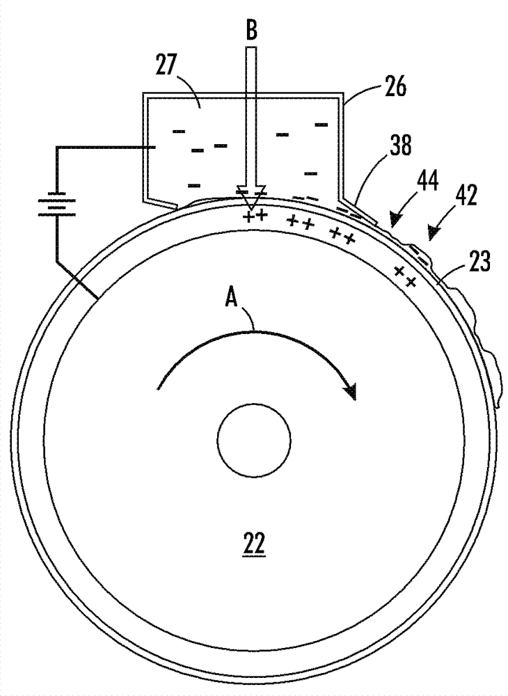
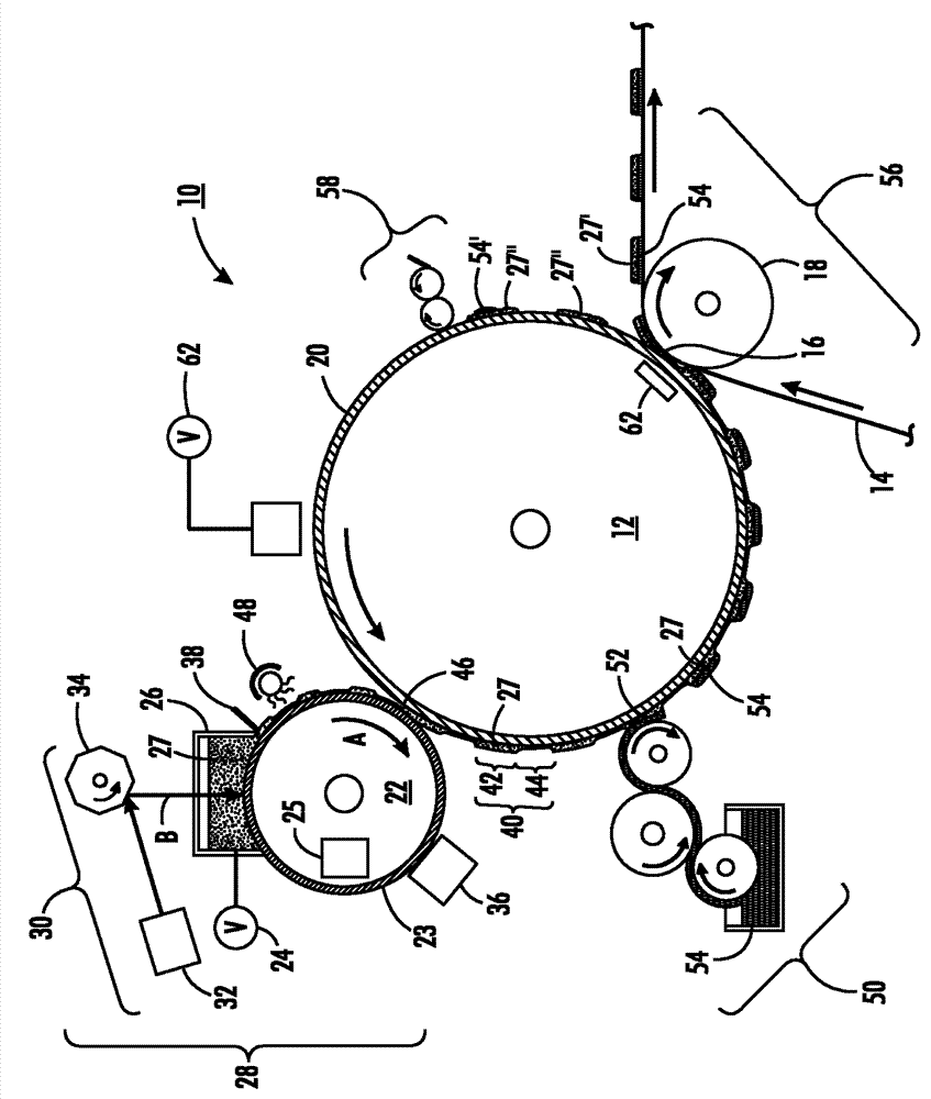
[0034] refer to figure 1 , in which is shown a system 10 for electrophotographic patterning of image definition materials according to one implementation of the present disclosure. System 10 includes an imaging component 12, in this implementation a drum, but could equally be a plate, belt, etc., surrounded by several subsystems described in detail below. Imaging member 12 applies an ink image to substrate 14 at nip 16 where substrate 14 is sandwiched between imaging member 12 and pressure roller 18 . A wide variety of substrate types can be used, such as paper, plastic or synth...


PUM


Abstract

A system comprises an electro-wetting subsystem, a transfer subsystem, an imaging member, and an inking subsystem. The electro-wetting subsystem comprises a photo-responsive photoreceptor, a charging mechanism, an image definition material reservoir, a charge erase mechanism, and an exposure subsystem, such as a light source and rotating polygon forming a raster output scanner (ROS) disposed for exposure of the photoreceptor through the image definition material reservoir. The imaging member comprises a reimageable surface having certain properties, such as having a low surface energy to promote ink release onto a substrate. In operation, the photoreceptor is charged areawise. An exposure pattern is formed by the exposure subsystem on the surface of the charged photoreceptor, which is developed with image definition material. The image definition material pattern is transferred to the reimageable surface. The pattern is developed with ink. The inked image may be transferred to a substrate.

Description

technical field [0001] The present disclosure relates to marking and printing methods and systems, and more particularly to methods and systems for variably marking or printing data using lithographic and electrophotographic systems and methods. Background technique [0002] Lithography is the usual printing method today. (For purposes here, the terms "print" and "mark" are interchangeable.) In typical lithography, a printing plate (which can be a flat plate, the surface of a cylinder, or a belt, etc.) is printed Formed to have an "image area" formed of a hydrophobic and lipophilic material, and a "non-image area" formed of a hydrophilic material. The image area is the area corresponding to the area on the final print (i.e. the target substrate) occupied by printing or marking material such as ink, while the non-image area is the area corresponding to the area on the final print not covered by The area of ​​the area occupied by the marking material. The hydrophilic area a...

Claims


Application Information

Patent Timeline
Patent Type & Authority Applications(China)
IPC IPC(8): G03G15/00G03G15/10G03G15/18
CPCG03G15/10G03G13/28G03G15/226
Inventor J.维勒斯D.K.比格尔森
Owner PALO ALTO RES CENT INC
Why Eureka
Try Eureka