Stator end electric shielding structure of synchronous generator

A synchronous generator, stator end technology, applied in the direction of preventing/reducing eddy current loss in the winding head, etc., can solve the problems of burning out the stator pressure ring and rotor guard ring, heat generation, etc., to achieve simple structure and reduce magnetic flux leakage , the effect of reducing heat

Inactive Publication Date: 2014-01-29
SEC ELECTRIC MACHINERY
View PDF7 Cites 7 Cited by
  • Summary
  • Abstract
  • Description
  • Claims
  • Application Information

AI Technical Summary

Problems solved by technology

[0002] During the operation of a large-capacity high-speed synchronous generator, due to the large current, the end of the stator coil will generate a large magnetic flux leakage. Heat, in severe cases, will burn out the stator pressure ring and rotor retaining ring

Method used


Image

  • Stator end electric shielding structure of synchronous generator

Examples


Embodiment Construction

[0011] The specific embodiments of the present invention will be further described below in conjunction with the accompanying drawings.

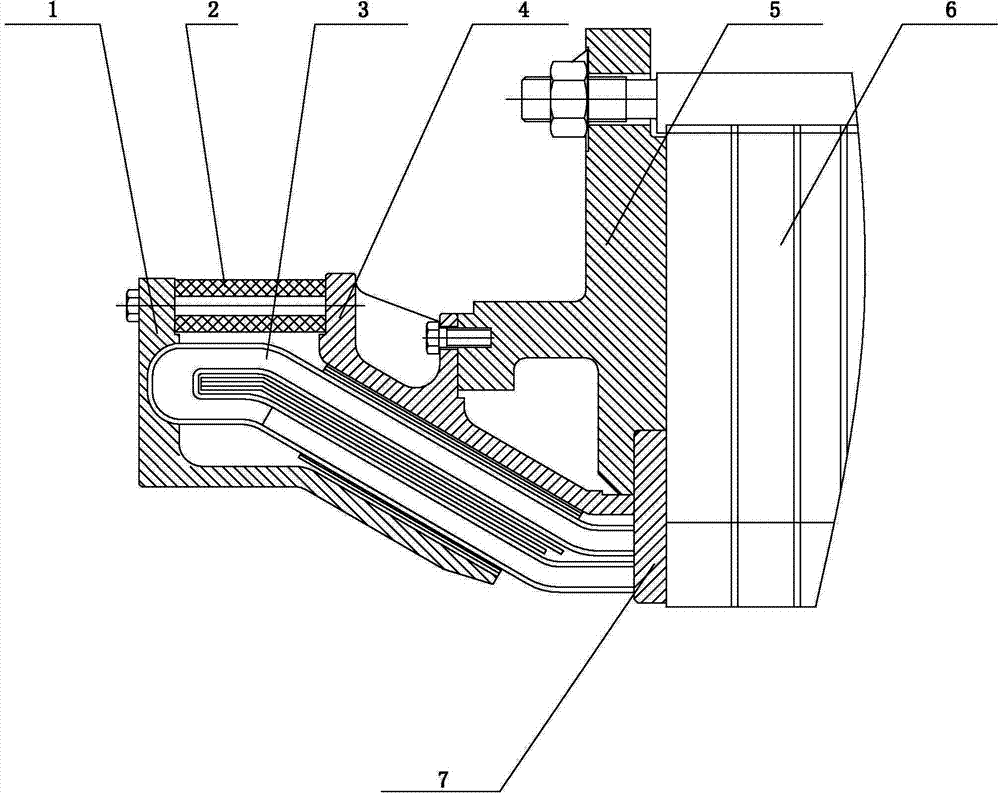
[0012] Such as figure 1 As shown, the present invention includes an outer shielding ring 1 , a pad 2 , a stator coil 3 , an inner shielding ring 4 , a stator pressure ring 5 and a stator tooth pressure plate 7 . The stator pressure ring 5 compresses the stator tooth pressure plate 7, and is fixed on the end of the stator iron core 6 with bolts. The inner shielding ring 4 is fixed on the stator pressure ring 5 with bolts. The outer shielding ring 1 is fixed with the inner shielding ring 4 by bolts and pads 2 . The end of the stator coil 3 is placed between the inner shielding ring 4 , the outer shielding ring 1 and the stator tooth pressure plate 7 .

[0013] The inner shielding ring 4, the outer shielding ring 1 and the stator tooth pressure plate 7 are all made of non-magnetic material copper, which reduces the magnetic flux leakage at t...


PUM


Abstract

The invention discloses a stator end electric shielding structure of a synchronous generator. The stator end electric shielding structure of the synchronous generator comprises an outer shielding ring, a cushion block, a stator coil, an inner shielding ring, a stator pressing ring and a stator tooth support. The stator pressing ring compresses the stator tooth support and is fixed on the end portion of a stator core through bolts, the inner shielding ring is fixed on the stator pressing ring through bolts, and the outer shielding ring is fixed with the inner shielding ring through bolts and the cushion block. The end portion of the stator coil is placed among the inner shielding ring, the outer shielding ring and the stator tooth support. The inner shielding ring, the outer shielding ring and the stator tooth support are made of nonmagnetic material copper. The stator end electric shielding structure of the synchronous generator is simple in structure and high in reliability, magnetic leakage on the end portion of the stator coil is reduced, heating of the stator pressing ring and heating of a rotor retaining ring are reduced, and the operation reliability of the synchronous generator is improved.

Description

technical field [0001] The invention relates to a synchronous generator, in particular to a stator end electric shielding structure for a large-capacity high-speed synchronous generator. Background technique [0002] During the operation of a large-capacity high-speed synchronous generator, due to the large current, the end of the stator coil will generate a large magnetic flux leakage. The heat will burn out the stator pressure ring and the rotor retaining ring in severe cases. Contents of the invention [0003] The purpose of the present invention is to solve the above problems and provide an electric shielding structure at the stator end of a synchronous generator. This structure not only has a simple manufacturing process, but also improves the reliability of the motor operation. [0004] Technical scheme of the present invention is as follows: [0005] An electrical shielding structure at the stator end of a synchronous generator, including an outer shielding ring, ...

Claims


Application Information

Patent Timeline
Patent Type & Authority Applications(China)
IPC IPC(8): H02K3/42
Inventor 胡攀王岗
Owner SEC ELECTRIC MACHINERY
Why Eureka
Try Eureka