Extrusion moulding method for parts with inner flanges and outer flanges and extrusion mould

An extrusion die and extrusion forming technology, applied in the direction of metal extrusion dies, etc., can solve the problems of high mold manufacturing cost, cumbersome forming process, difficult forming, etc., to improve utilization rate, simple forming process, and reduce production cost Effect

Active Publication Date: 2014-02-05
HENAN UNIV OF SCI & TECH
View PDF6 Cites 13 Cited by
  • Summary
  • Abstract
  • Description
  • Claims
  • Application Information

AI Technical Summary

Problems solved by technology

But for parts with inner flange and outer flange at the same time, this part includes sleeve section and ring-shaped outer flange section provided at one end of sleeve section, and the inner flange section extending along its axial direction is opened on the outer flange section. hole, the centerline of the inner hole of the outer flange section coincides with the centerline of the center hole of the sleeve section, the diameter of the center hole of the sleeve section is larger than the diameter of the inner hole of the outer flange section, the center hole of the sleeve section and the outer The connection of the inner hole of the flange section forms an inner flange, and the central hole of the sleeve section is connected with the inner hole of the outer flange section to form a stepped inner hole of the part. When this part is extruded, the extrusion die used The structure is complex, the forming process is cumbersome, the mold processing and manufacturing cost is high, and the inner hole of this part is a stepped inner hole, which is difficult to form during extrusion processing. After the extrusion is completed, necessary machining is required to obtain the final part. Thereby causing waste of materials and reducing the utilization rate of materials

Method used


Image

  • Extrusion moulding method for parts with inner flanges and outer flanges and extrusion mould
  • Extrusion moulding method for parts with inner flanges and outer flanges and extrusion mould
  • Extrusion moulding method for parts with inner flanges and outer flanges and extrusion mould

Examples


Embodiment Construction

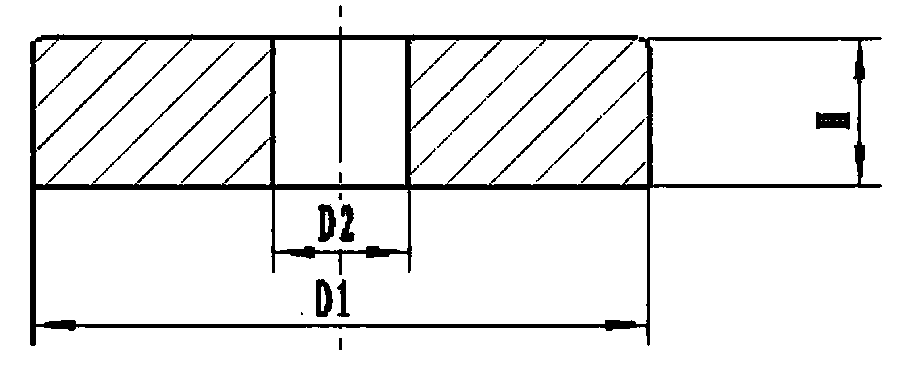
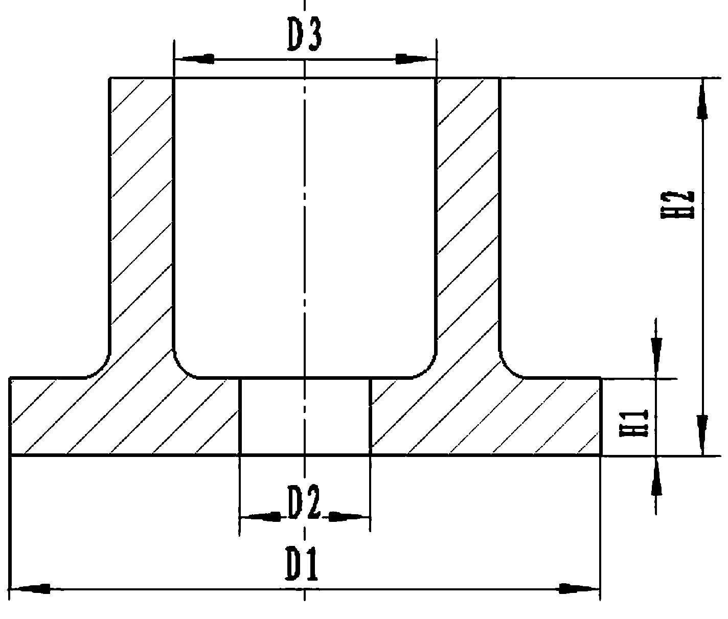
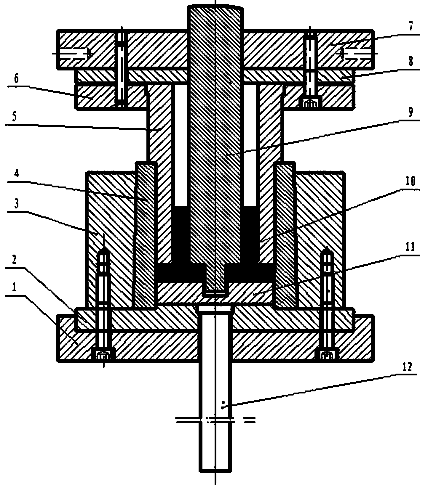
[0020] A kind of embodiment of the extrusion molding method of the parts with inner and outer flanges of the present invention: as image 3 As shown, the extrusion molding method includes the following steps, 1) will be as figure 1 The billet shown is put into the die 4 of the extrusion die installed on the double-acting hydraulic press. The outer diameter of the billet is D1, the outer diameter is equal to the flange diameter of the required part, the inner diameter is D2, and the inner diameter is the same as the required part The diameters of the small-diameter sections of the inner holes are equal, and the height is H. The first loading mechanism is the inner cylinder loading of the double-acting hydraulic press, and the second loading mechanism is the outer cylinder loading mechanism. The extrusion die includes an inner punch 9, and the inner punch The lower end of the 9 is provided with a stepped shaft structure with a small lower end and a large upper end. The inner pun...


PUM


Abstract

The invention relates to an extrusion moulding method for parts with inner flanges and outer flanges and an extrusion mould. The extrusion moulding method of the parts comprises the following steps: 1, placing a blank material in a female die, wherein the extrusion mould comprises an internal male die and an external male die sleeved on the periphery of the internal male die, a step shaft structure is arranged at the lower end of the internal male die, an annular moulding gap is formed between the external male die and the internal male die; 2, driving the internal male die to downwards move for extruding the blank material through a first loading mechanism which is in transmission connection with the internal male die, extruding an inner hole, enabling a step surface of a step shaft structure at the lower end of the internal male die to be supported against the blank material to keep stable, driving the external male die to downwards move to extrude the blank material through a second loading mechanism which is in transmission connection with the external male die until extruding a required part; and 3, completing the extrusion, wherein the loading mechanism drives the internal male die and the external male die to return to take the formed part out. According to the extrusion moulding method, the internal male die and the external male die are respectively driven to form the step-shaped inner hole and the outer flange part, the process is simple, the material utilization ratio is high, and the production cost is low.

Description

technical field [0001] The invention relates to the technical field of metal extrusion forming, in particular to an extrusion forming method and an extrusion die of parts with inner and outer flanges. Background technique [0002] Flange parts are generally cast, forged or extruded first, and then the formed parts are machined to obtain the final product. But for parts with inner flange and outer flange at the same time, this part includes sleeve section and ring-shaped outer flange section provided at one end of sleeve section, and the inner flange section extending along its axial direction is opened on the outer flange section. hole, the centerline of the inner hole of the outer flange section coincides with the centerline of the center hole of the sleeve section, the diameter of the center hole of the sleeve section is larger than the diameter of the inner hole of the outer flange section, the center hole of the sleeve section and the outer The connection of the inner h...

Claims


Application Information

Patent Timeline
Patent Type & Authority Applications(China)
IPC IPC(8): B21C23/02B21C25/02
Inventor 宋克兴国秀花王庆福周延军张学宾赵培峰张彦敏贾淑果李红霞何霞张素霞赵亚永
Owner HENAN UNIV OF SCI & TECH
Why Eureka
Try Eureka