

Anti-skid device for automobile
An anti-skid device, a technology for automobiles, applied in the directions of wheels, wheel accessories, vehicle parts, etc., can solve problems such as trouble, danger, and traffic accidents caused by drivers, and achieve good anti-skid effect, increased safety, and increased friction. Effect
- Summary
- Abstract
- Description
- Claims
- Application Information
AI Technical Summary
Problems solved by technology
Method used
Image

Examples
Embodiment Construction
[0011] The present invention will be described in further detail with reference to the accompanying drawings.
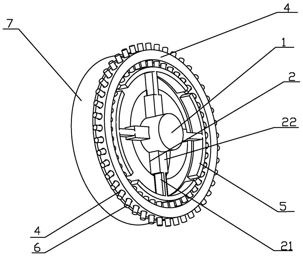
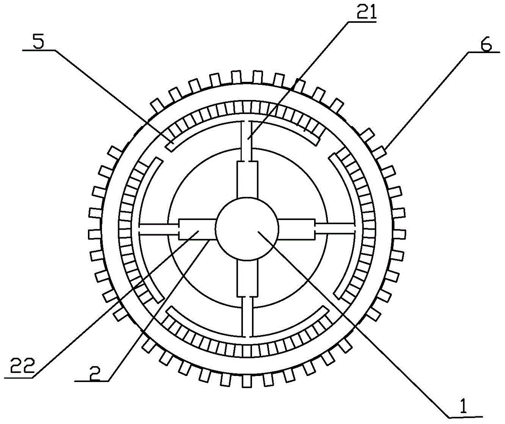
[0012] Such as figure 1 Shown: a kind of automobile antiskid device, comprises automobile axle 1, telescopic device 2 and an annular part 3, and its height of described annular part 3 is identical with automobile wheel 4, and the outer edge of described annular part is exactly the same as that of automobile wheel. The wheels are flush and bolted to the outer edge of the car wheel.
[0013] The annular part 3 is provided with several punching holes 4 at intervals; the telescopic device 2 is composed of a telescoping rod 21 and a hydraulic cylinder 22, and the telescoping rod 21 is arranged inside the hydraulic cylinder 22, and the hydraulic cylinder is arranged on an automobile On the side wall of the automobile wheel 4 centered on the wheel shaft 1, an arc-shaped plate 5 is connected to the top of the telescopic rod 21, and the anti-skid nails 6 arranged regularly a...
PUM
 Abstract
Description
Claims
Application Information