Measuring method for displacement efficiency of simulated well cementation cementing

A technology of displacement efficiency and measurement method, which is applied in the direction of measurement, measurement device, fluid velocity measurement, etc., can solve the problems of displacement efficiency error, measurement method limitation, lack of replacement liquid and the replacement process of the displaced liquid, etc., to achieve investment Low cost, good versatility, and the effect of eliminating errors

Active Publication Date: 2014-02-05
CHINA PETROLEUM & CHEM CORP +1
View PDF8 Cites 10 Cited by
  • Summary
  • Abstract
  • Description
  • Claims
  • Application Information

AI Technical Summary

Problems solved by technology

The measurement methods of these simulation devices have their own advantages, but their common disadvantages are: only the results of the displacement efficiency of the displacement fluid to the displaced fluid can be obtained, but the flow state of the displacement fluid in the flow field cannot be truly grasped. The whole process of replacing the displaced liquid by the displacing liquid is not conducive to ensuring the accuracy and reliability of the displacing efficiency, and there is a certain error in the obtained displacing efficiency; in addition, the measurement methods of these simulation devices are very limited and cannot be used universally

Method used


Image

  • Measuring method for displacement efficiency of simulated well cementation cementing

Examples


Embodiment Construction

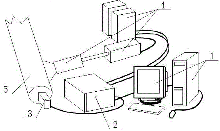
[0017] See figure 1 , The present invention includes the following steps:

[0018] 1). Taking the PIV system including the computer 1, the signal processor 2, the CCD camera 3 and the laser 4 as the measuring equipment, the CCD camera 3 of the PIV system is required to be arranged on the top of the simulated wellbore 5, and the laser 4 of the PIV system is arranged on the simulated wellbore The measurement section of 5 makes the CCD camera 3 and the laser 4 perpendicular to each other when measuring the flow field;

[0019] 2). Inject the displaced fluid (mud-similar fluid) and displacement fluid (cement-slurry-similar fluid) into the annulus formed by the casing and wellbore of the simulated wellbore 5. The displaced fluid and the displacement fluid are required to be transparent, and Disperse tracer particles in the flow field of the displacement fluid;

[0020] 3). The laser 4 of the PIV system emits a piece of light that illuminates the flow field measurement area, so that the ...


PUM


Abstract

The invention relates to a measuring method for displacement efficiency of simulated well cementation cementing, which comprises the following steps: 1) taking a PIV (Particle Image Velocimetry) system as a measuring device; 2) respectively injecting a displaced solution and a displacing solution into a simulated shaft and distributing tracer particles in a displacing solution flow field; 3) causing the tracer particles to generate scattered light through a laser of the PIV system, and shooting and recording the positions of the tracer particles in the flow field in real time by using a CCD (Charge Coupled Device) camera of the PIV system; 4) obtaining a moving image of the tracer particles in the flow field, selecting a group at equal intervals from the moving image as analysis identifying information, and obtaining the areas occupied by the tracer particles in different time periods in an annular cross section of the simulated shaft; 5) obtaining the displacement efficiency of the displacing solution for the displaced solution in a certain time period according to the total area of the annular cross section of the simulated shaft and the data obtained through analysis identification; and 6) drawing a displacement efficiency graph through the obtained displacement efficiency in the simulated shaft in different time periods, thereby obtaining the whole displacement efficiency in the simulated shaft.

Description

Technical field [0001] The invention relates to a measuring method for simulating cement injection displacement efficiency. Background technique [0002] The construction operation of running casing into the well and injecting cement into the annular space between the wellbore and the casing is called cementing, which is an important operation in the drilling process. In order to grasp the displacement efficiency of cement injection under various well conditions and to inject suitable cement into the well, it is necessary to simulate the displacement efficiency of cement injection under various well conditions before the cementing operation. At present, there are many simulation devices designed for the efficiency of cement injection displacement. Among them, the most widely used are the full-scale displacement simulation experimental device, the actual density cement slurry and similar-sized casing displacement experimental device, and similar liquid simulation small gap Displa...

Claims


Application Information

Patent Timeline
Patent Type & Authority Applications(China)
IPC IPC(8): E21B47/00E21B33/138G01P5/20
Inventor 欧彪徐壁华顾战宇严焱诚朱礼平龙刚肖国益何志辉薛丽娜李果朱化蜀谢应权胡大梁房舟
Owner CHINA PETROLEUM & CHEM CORP
Why Eureka
Try Eureka