Method and device for detecting failure of urea injection system

A urea injection system and urea injection technology are applied in the direction of electric control of exhaust treatment devices, diagnostic devices of exhaust treatment Plug-in installation is not firm and other problems, to achieve a good control effect

Active Publication Date: 2017-07-28
WEICHAI POWER CO LTD
View PDF5 Cites 0 Cited by
  • Summary
  • Abstract
  • Description
  • Claims
  • Application Information

AI Technical Summary

Problems solved by technology

[0003] In the existing air-assisted urea injection system, sometimes the SCR urea pump is in good working condition, the auxiliary air pressure is normal, and the relevant CAN communication parameters required for urea injection are received normally, but the discharge results become worse
The analysis found that it is generally caused by mechanical failures in the connecting pipelines of the urea injection system components, such as damage to the urea suction pipeline, such as high temperature melting, leaking connectors that are not installed firmly, or blockage of the outlet of the urea tank, resulting in the failure of the urea pump to meet the requirements. Pump enough urea solution
This mechanical failure cannot be detected by the urea injection system, which results in the inability to control engine nitrogen and oxygen emissions in this failure mode

Method used


Image

  • Method and device for detecting failure of urea injection system
  • Method and device for detecting failure of urea injection system
  • Method and device for detecting failure of urea injection system

Examples


Embodiment 1

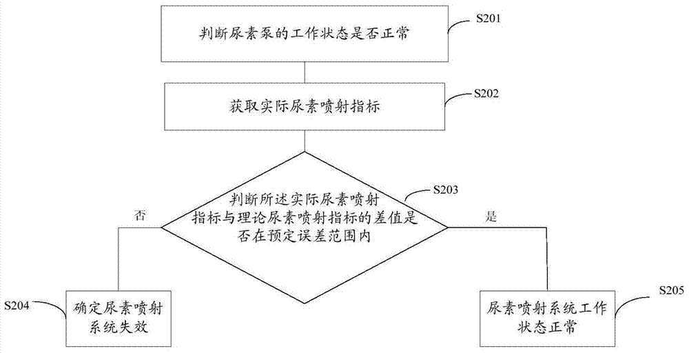
[0036] figure 2 It is a schematic flowchart of the detection method for failure of the urea injection system in Embodiment 1 of the present invention.

[0037] S201, judging whether the working state of the urea pump is normal:

[0038] Specifically, by checking whether the CAN bus communication of the urea injection system is normal, whether the auxiliary air pressure is normal, etc., it is judged whether the working state of the urea pump is in good condition. If it is determined that the working state of the urea pump is normal, step S202 is executed.

[0039] S202. Obtain the actual urea injection index:

[0040] It should be noted that the urea injection index described in this embodiment is a representation of the amount of urea injected by the urea injection system. Specifically, the urea injection index can be the urea injection amount under predetermined working conditions, or the urea injection pressure of the urea pump at a predetermined operating frequency, or ...

Embodiment 2

[0078] see Figure 4 , Figure 4 It is the detection device for the failure of the urea injection system in the second embodiment. The detection device includes,

[0079] The first determination unit 41 is configured to determine that the urea pump is in a normal injection state;

[0080] An acquisition unit 42, configured to acquire an actual urea injection index;

[0081] A judging unit 43, configured to judge whether the difference between the actual urea injection index and the theoretical urea injection index is within a predetermined error range;

[0082] The second determining unit 44 is configured to determine that the urea injection system fails when the difference between the actual urea injection index and the theoretical urea injection index is not within a predetermined error range.

[0083] Further, the urea injection index includes the urea injection amount at the outlet of the urea pump.

[0084] Further, the urea injection index includes, under predetermi...


PUM


Abstract

The invention provides a method and a device for detecting failures of a urea spraying system. The method includes determining that the working state of a urea pump is normal; acquiring an actual urea spraying index which shows urea spraying quantity of the urea spraying system; judging whether a difference value between the actual urea spraying index and a theoretical urea spraying index is within a preset error range or not, if not, determining that the urea spraying system is in a failure. By the method and the device, the failures, of the urea spraying system, caused by mechanical failures of spraying part connecting pipelines can be detected, so that the mechanical failures can be found timely, and exhaust gas emission indexes of an engine can be controlled better.

Description

technical field [0001] The invention relates to the technical field of engine exhaust emissions, in particular to a method and device for detecting failure of a urea injection system. Background technique [0002] SCR (Selective Catalytic Reduction) technology is one of the main post-treatment technologies for eliminating nitrogen oxides in diesel engine exhaust. According to the function, it is mainly divided into three parts: control unit, urea dosage unit and catalytic reaction unit; the urea dosage unit can be divided into air-assisted urea injection system and non-air-assisted urea injection system according to whether there is air-assisted injection. [0003] In the existing air-assisted urea injection system, sometimes the SCR urea pump is in good working condition, the auxiliary air pressure is normal, and the relevant CAN communication parameters required for urea injection are received normally, but the discharge result becomes worse. The analysis found that it is...

Claims


Application Information

Patent Timeline
Patent Type & Authority Patents(China)
IPC IPC(8): F01N11/00
CPCY02T10/40
Inventor 王奉双刘伟达侯亚玲王瑞冯文文
Owner WEICHAI POWER CO LTD
Why Eureka
Try Eureka