A hydraulic constant-speed power generation system for a multi-layer split-flow vertical axis fan

A vertical axis, hydraulic technology, applied in the field of multi-layer shunt type vertical axis fan hydraulic constant speed power generation system, can solve the problems of low wind energy utilization rate, insufficient flow, energy loss, etc., and achieve high wind energy utilization rate, high utilization efficiency, The effect of simple structure

Inactive Publication Date: 2016-03-02
TAIHE WAVE ENERGY RES CENT QINGDAO ECONOMIC TECH DEV ZONE
View PDF4 Cites 0 Cited by
  • Summary
  • Abstract
  • Description
  • Claims
  • Application Information

AI Technical Summary

Problems solved by technology

Although the above-mentioned patent can change the speed of the pump, because it is equipped with a single generator, it can only generate electricity in one state. When it is greater than or equal to the rated wind speed, there is no problem; but when it is lower than the rated wind speed, due to insufficient flow , cannot provide the torque required by the generator, so it has to stop, so a large part of wind energy is wasted, and the utilization rate of wind energy is low
In addition, it uses a step-up gearbox, which will cause energy loss in the system due to the mechanical efficiency of the gears
At the same time, due to the use of horizontal-axis wind turbines, it is difficult to arrange multiple layers and cannot develop to high altitudes. It is impossible to make full use of the favorable conditions that the higher the wind speed, the more stable it is. In addition, most of the existing ordinary vertical-axis wind turbines use direct drive. If the permanent magnet generator is to be connected to the grid, it needs corresponding controllers and inverters. At present, the cost of the direct drive permanent magnet generator is the direct cause of hindering its large-scale and commercialization.

Method used


Image

  • A hydraulic constant-speed power generation system for a multi-layer split-flow vertical axis fan
  • A hydraulic constant-speed power generation system for a multi-layer split-flow vertical axis fan
  • A hydraulic constant-speed power generation system for a multi-layer split-flow vertical axis fan

Examples


Embodiment Construction

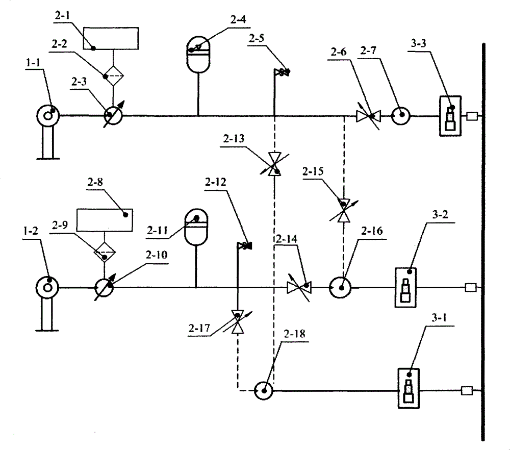
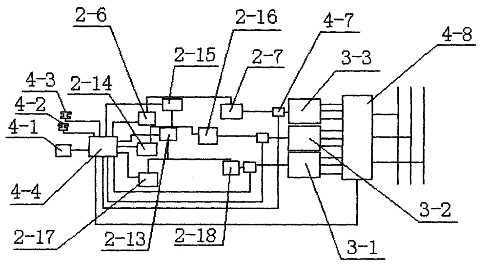
[0017] refer to figure 1 , figure 2 with image 3 A hydraulic constant-speed power generation system of a multi-layer shunt type vertical axis fan is shown, including a fan part, a hydraulic part, a power generation part and a control part, the fan part is connected to the hydraulic part, the hydraulic part is connected to the power generation part, and the The above-mentioned control part is respectively connected with the fan part, the hydraulic part and the power generation part.

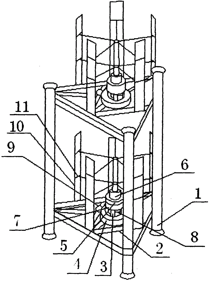
[0018] As a preferred technical solution, the fan part consists of a vertical axis wind wheel (10), a wind wheel flange (9), a wind wheel bearing seat (8), a wind wheel bearing cover (7), a bearing (6), a coupling device (11), coupling flange (5), hydraulic pump flange (3), hydraulic pump mounting plate (4), mounting base plate (2) and multi-layer tower (1), the coupling (11) Installed on the shaft of the vertical axis wind wheel (10), the wind wheel bearing seat (8), the wind wheel bearing c...


PUM


Abstract

The invention relates to a hydraulic constant-speed generating system of a multilayer shunting type vertical axial fan. The hydraulic constant-speed generating system comprises a fan part, a hydraulic part, a generating part and a control part, wherein the fan part is connected with the hydraulic part which is connected with the generating part, and the control part is respectively connected with the fan part, the hydraulic part and the generating part. The hydraulic constant-speed generating system of the multilayer shunting type vertical axial fan has the advantages of simple structure, convenience in use and installation, simplicity in operation, orderly start in multilayer shunting, high utilization efficiency, orderly control in coordination, simplicity in control, high utilization rate of wind energy, good self-starting effect of wind wheels, safety and reliability.

Description

technical field [0001] The invention relates to a hydraulic constant-speed power generation system of a multi-layer split-flow vertical-axis fan. Background technique [0002] As a kind of renewable energy, wind energy has abundant reserves in China. According to the National Meteorological Administration, China's total wind energy reserves at a height of 10 meters above the ground are about 3.226 billion kilowatts, of which 253 million kilowatts of wind energy reserves can be developed and utilized on land. times, more than 500 million kilowatts. With the increasing awareness of wind power generation and the continuous maturity of wind power generation technology, its application fields are becoming more and more extensive. [0003] Although the current vertical axis wind turbine can receive wind from any direction, it has a non-increasing gearbox, and the generator can be installed on the ground, and it is easy to maintain, and it is gradually being valued. However, the...

Claims


Application Information

Patent Timeline
Patent Type & Authority Patents(China)
IPC IPC(8): F03D9/17F03D7/06F03D3/00F03D13/20F03D17/00
CPCY02E10/728Y02E10/74Y02E60/16Y02E70/30Y02P80/10
Inventor 孙明刚张立军刘华张鹏鹏
Owner TAIHE WAVE ENERGY RES CENT QINGDAO ECONOMIC TECH DEV ZONE
Why Eureka
Try Eureka