
Self-generating liquid hourglass lamp

An hourglass lamp and self-generating technology, which is applied to semiconductor devices of light-emitting elements, electric light sources, and internal power supplies, etc., can solve the problems of hourglasses that can only generate electricity in one direction, pollute the shaft, reduce the capacity of quicksand, etc., and achieve fun And the effect of ornamental and reasonable structure

Inactive Publication Date: 2014-02-05
CHENGDU UNIVERSITY OF TECHNOLOGY
View PDF7 Cites 8 Cited by
  • Summary
  • Abstract
  • Description
  • Claims
  • Application Information

AI Technical Summary

Problems solved by technology

[0003] The Chinese patent with the publication number CN 203223854 U provides an hourglass lamp that drives a power generating device fixed on the bottle body to generate electricity when sand falls. This design enables the hourglass lamp to have a self-generating function, but its disadvantages are: 1. Reduce 2. The hourglass can only generate electricity in one direction, 3. It is easy to cause shaft pollution

Method used


Image

  • Self-generating liquid hourglass lamp
  • Self-generating liquid hourglass lamp
  • Self-generating liquid hourglass lamp

Examples


no. 1 example

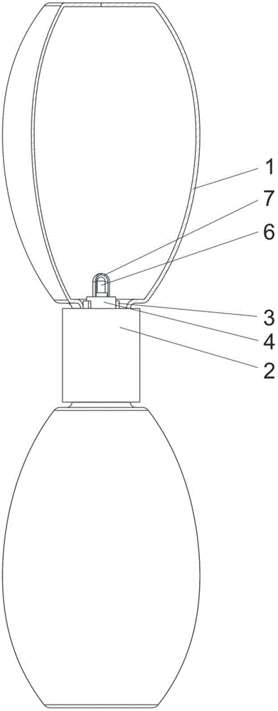
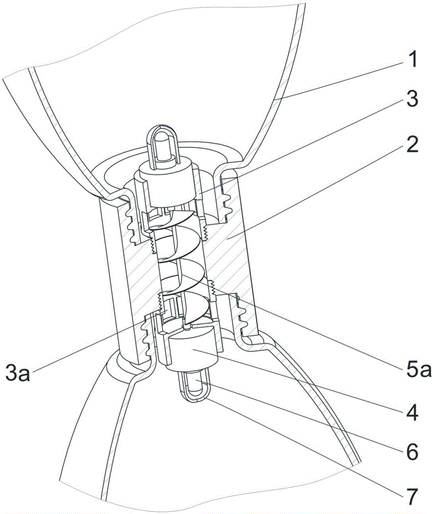
[0015] The first embodiment: as figure 1 , figure 2 As shown, the lamp housing 1 is a container with a neck made of two pieces of glass. The neck is provided with external threads, and the lamp housing 1 is filled with water. The stepped hole is connected with the axis. The large hole and the small hole of the stepped hole are respectively provided with internal threads, and the internal thread of the large hole is used to cooperate with the external thread of the neck to connect the two lamp housings 1 into one. The power generating device is composed of a generator 4 and a helical blade 5a, and the central axis of the helical blade 5a is connected with the rotating shaft of the generator 4 . The machine cover 3 is a tubular piece with a partition in the middle, and one end is provided with an external thread, which is connected with the small hole internal thread of the connector 2. The generator 4 is placed in one end of the hood 3 , the generator shaft passes through t...

no. 2 example

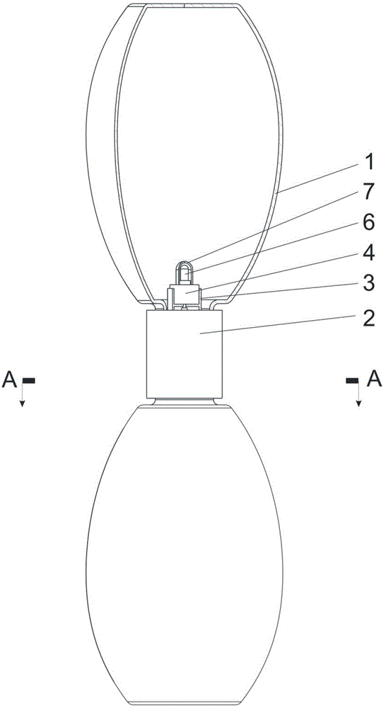
[0017] The second embodiment: as image 3 , Figure 4 , Figure 5 As shown, the lamp housing 1 is a container with a neck made of two pieces of glass. The neck is provided with external threads, and the lamp housing 1 is filled with water. The stepped hole is connected with the axis, and the large hole of the stepped hole is provided with an internal thread, and the internal thread of the large hole is used to cooperate with the external thread of the neck to connect the two lamp housings 1 into one. The power generating device is composed of a generator 4 and an impeller 5b, and the central axis of the impeller 5b is connected with the rotating shaft of the generator 4 . The machine cover 3 is a tubular piece with a partition in the middle, and one end is bonded with the end face of the small hole of the connector 2 . The generator 4 is placed in the other end of the hood 3, the generator shaft passes through the hood partition, and after being connected with the central...


PUM


Abstract

The invention discloses a self-generating liquid hourglass lamp. The self-generating liquid hourglass lamp comprises lamp housings, a connecting piece, generating devices and electric lamps, wherein the lamp housings are two containers made of light-transmitting materials and provided with openings, a flow medium of the hourglass lamp is liquid, the connecting piece is used for connecting the two lamp housing openings, so that the two lamp housings are integrally connected, the connecting piece is provided with a liquid channel and the generating devices, the liquid in the lamp housings can flow between the two lamp housings through the channel, the generating device can be driven to work when the liquid flows, and the electric lamps are arranged in the lamp housings and connected with the generating devices through wires. The self-generating liquid hourglass lamp is reasonable in structure, energy-saving and environment-friendly, can emit light in the liquid and is interesting and ornamental.

Description

technical field [0001] The invention relates to a liquid self-generating device, in particular to a self-generating fluid hourglass lamp. Background technique [0002] The hourglass is an ancient timekeeping tool consisting of two conical containers connected by which sand from the upper container flows into the bottom container to measure time. Today's hourglass is a kind of decoration, and there are a large number of different types of hourglass products on the market, some are used for decoration, and some are used for children's toys, but an hourglass device that can generate electricity by itself has not yet been found. There are also some design documents related to the hourglass lamp, such as the Chinese patent, the hourglass lamp whose publication number is CN 202747300 U, which is a device that utilizes the form of an hourglass to perform luminous timing. And the hourglass lamp whose publication number is CN 203024021 U is a device that utilizes the amount of sand ...

Claims


Application Information

Patent Timeline
Patent Type & Authority Applications(China)
IPC IPC(8): F21S9/04F21Y101/02F21Y115/10
Inventor 杨勇向军甘力涵邓伟林
Owner CHENGDU UNIVERSITY OF TECHNOLOGY
Learn More