Mandibular Protrusion Distance Measuring Device
A technology of distance measurement and mandible, which is applied in the field of mandibular protrusion distance measurement device, which can solve the problem that oral appliances cannot conveniently and accurately determine the mandibular protrusion distance, and achieve the effect of convenient use
- Summary
- Abstract
- Description
- Claims
- Application Information
AI Technical Summary
Problems solved by technology
Method used
Image
Examples
Embodiment 1
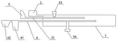
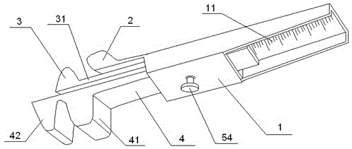
[0022] refer to figure 1 , the mandibular protruding distance measuring device provided by the present invention comprises a rectangular parallelepiped hollow box body 1, the two ends of the box body 1 are open, and one end of the box body 1 is provided with a protruding block as the upper tooth external fixer 2, and the upper tooth is externally fixed Part 2 is fixedly connected with box body 1. In addition, an upper tooth internal fixation part 3 is provided, and a groove for inserting the upper incisors is formed between the upper tooth external fixation part 2 and the upper tooth internal fixation part 3 .
[0023] It also includes the measuring ruler 4 and the lower tooth internal fixation part 42 and the lower tooth external fixation part 41 at the head end of the measuring ruler, and the groove for inserting the lower incisors is formed between the lower tooth internal fixation part 42 and the lower tooth external fixation part 41. The other end of measuring ruler 4 is...
Embodiment 2
[0027] refer to figure 2 , on the basis of Embodiment 1, the lower surface of the box body 1 away from the lower tooth external fixation piece is open, and the inner wall of the upper surface is exposed, and the inner wall of the upper surface is provided with a length scale. Bite your back teeth lightly. The doctor observed the patient's anterior overbite coverage and the midline of the upper and lower dentition, and made records. The upper and lower incisors of the patient are respectively placed in the above-mentioned grooves. The doctor instructs the patient to relax the mandible as much as possible, and puts the hand on the chin to induce the patient to move the mandible backward and drive the measuring ruler 4 back until the mandible is in the maximum receded position. Record the scale D1 corresponding to the end of the measuring ruler, expressed as a negative number.
[0028] Then instruct the patient to protrude the mandible until the maximum protruding position, fi...
Embodiment 3
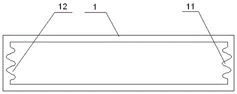
[0032] refer to image 3 and Figure 4 , in this embodiment, the inner walls of both sides of the box body 1 are provided with horizontal protruding strips 11, and grooves 12 are formed between the horizontal protruding strips 11. Both sides of the measuring ruler 4 are provided with chute 43 .
[0033] The protruding strip 11 is placed in the chute 43 , and both sides of the chute 43 are placed in the groove 12 , so the measuring ruler 4 can slide in the box body 1 .
[0034] In this embodiment, the number of raised strips 11 and grooves 12 can be multiple, such as image 3 shown. In this way, the vertical height of the lower measuring ruler can be set according to the patient's overlay, so that the mandible can flexibly protrude.
PUM
 Abstract
Description
Claims
Application Information
 - R&D
- Intellectual Property
- Life Sciences
- Materials
- Tech Scout
- Unparalleled Data Quality
- Higher Quality Content
- 60% Fewer Hallucinations
Browse by: Latest US Patents, China's latest patents, Technical Efficacy Thesaurus, Application Domain, Technology Topic, Popular Technical Reports.
© 2025 PatSnap. All rights reserved.Legal|Privacy policy|Modern Slavery Act Transparency Statement|Sitemap|About US| Contact US: help@patsnap.com


