Flanging and punching die

A punching and die technology, used in forming tools, manufacturing tools, metal processing equipment, etc., can solve the problems of increasing processes, unable to flange and complete side punching at the same time, saving processes and avoiding motion interference.

Inactive Publication Date: 2014-02-12
SAIC-GM-WULING AUTOMOBILE CO LTD
View PDF6 Cites 10 Cited by
  • Summary
  • Abstract
  • Description
  • Claims
  • Application Information

AI Technical Summary

Problems solved by technology

The traditional mold structure cannot realize the side punching at the same time as the upper flanging, and needs to be distributed in different processes to complete, and often requires additional processes because of the side punching

Method used


Image

  • Flanging and punching die
  • Flanging and punching die
  • Flanging and punching die

Examples


Embodiment Construction

[0015] The present invention will be further described below in conjunction with the accompanying drawings and specific embodiments.

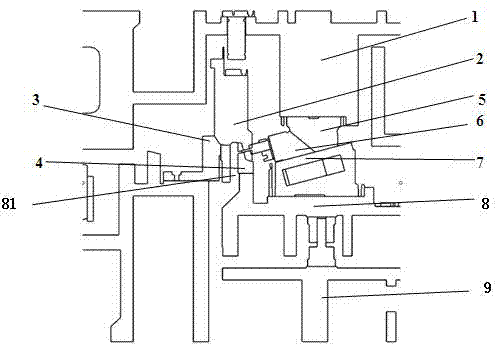
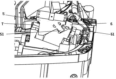
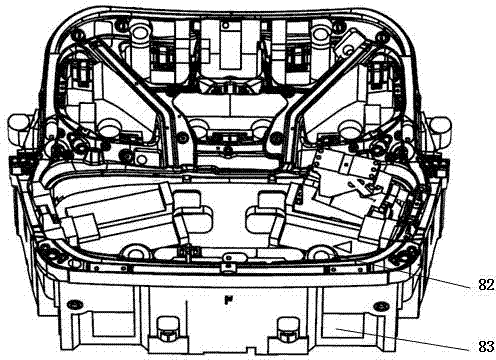
[0016] Figure 1 to Figure 3 The reference numerals in the figure are: upper mold base 1; upper mold pressing core 2; upper flanging knife block 3; lower mold side punching die insert 4; Forced retraction hook 51; side punching wedge 6; side punching wedge forced retraction groove 61; side punching wedge guide post 7; lower mold pressing core 8; punching waste sliding channel 81; guide plate 82; guide Hole 83; Lower mold base 9.

[0017] Such as Figure 1 to Figure 3 As shown, a flanging punching die includes an upper mold base 1 and a lower mold base 9, the upper mold base 1 is connected with an upper mold pressing material core 2, and the lower mold base 9 is connected with a lower mold pressing material core 8, The upper mold base 1 is connected with an upper mold side punching driving block 5, and the upper mold side punching driving blo...


PUM


Abstract

The invention provides a flanging and punching die. The flanging and punching die comprises an upper die base and a lower die base, wherein the upper die base is connected with an upper die pressing core, the lower die base is connected with a lower die pressing core, the upper die base is connected with an upper die lateral punching driving block, the upper die lateral punching driving block is provided with a lateral punching wedge forced rollback hook, the lower die pressing core is respectively connected with an upper flanging cutter block, a lower die lateral punching female die insert, a lateral punching wedge and a lateral punching wedge guide pillar, the lateral punching wedge and the lateral punching wedge guide pillar is a moving pair, the lateral punching wedge is provided with a lateral punching wedge forced rollback groove, the lateral punching wedge forced rollback hook is arranged in the lateral punching wedge forced rollback groove, the lateral punching wedge is connected with a lower die lateral punching male die insert, and the lower die lateral punching male die insert and the lower die lateral punching female die insert are matched with each other. The flanging and punching die has the advantages of achieving the purpose of simultaneously flanging and punching, and reducing work procedures.

Description

technical field [0001] The invention relates to a mold, in particular to a flanging punching mold. Background technique [0002] On large body panels such as Body Side Inner and Tail Gate Inner, there are often upward flanging, downward flanging and side openings at the same time due to the needs of the body structure function . The traditional mold structure cannot realize the side punching at the same time as the upper flanging, which needs to be distributed in different processes, and often requires additional processes because of the side punching. Contents of the invention [0003] In order to solve the problems in the prior art, the invention provides a flanging and punching die which can carry out flanging and punching simultaneously. [0004] The invention provides a flanging punching die, comprising an upper mold base and a lower mold base, the upper mold base is connected with an upper mold pressing material core, the lower mold base is connected with a lower m...

Claims


Application Information

Patent Timeline
Patent Type & Authority Applications(China)
IPC IPC(8): B21D37/10B21D35/00
Inventor 韦庆峰冯静乔晓勇
Owner SAIC-GM-WULING AUTOMOBILE CO LTD
Why Eureka
Try Eureka