
Pulse arc welding control method

A control method and pulsed arc technology, applied in arc welding equipment, welding equipment, manufacturing tools, etc., can solve the problems of large external inductance value and failure to maintain waveform

Active Publication Date: 2016-08-17
DAIHEN CORP
View PDF10 Cites 0 Cited by
  • Summary
  • Abstract
  • Description
  • Claims
  • Application Information

AI Technical Summary

Problems solved by technology

However, due to constraints on the layout in the factory, the value of the external inductance may increase in any case.
Also, when the workpiece is a large building, the external inductance value may increase
In such a case, the waveform of the welding current Iw cannot maintain the waveform of the figure (B)

Method used


Image

  • Pulse arc welding control method
  • Pulse arc welding control method
  • Pulse arc welding control method

Examples


Embodiment Construction

[0080] Hereinafter, embodiments of the present invention will be described with reference to the drawings.

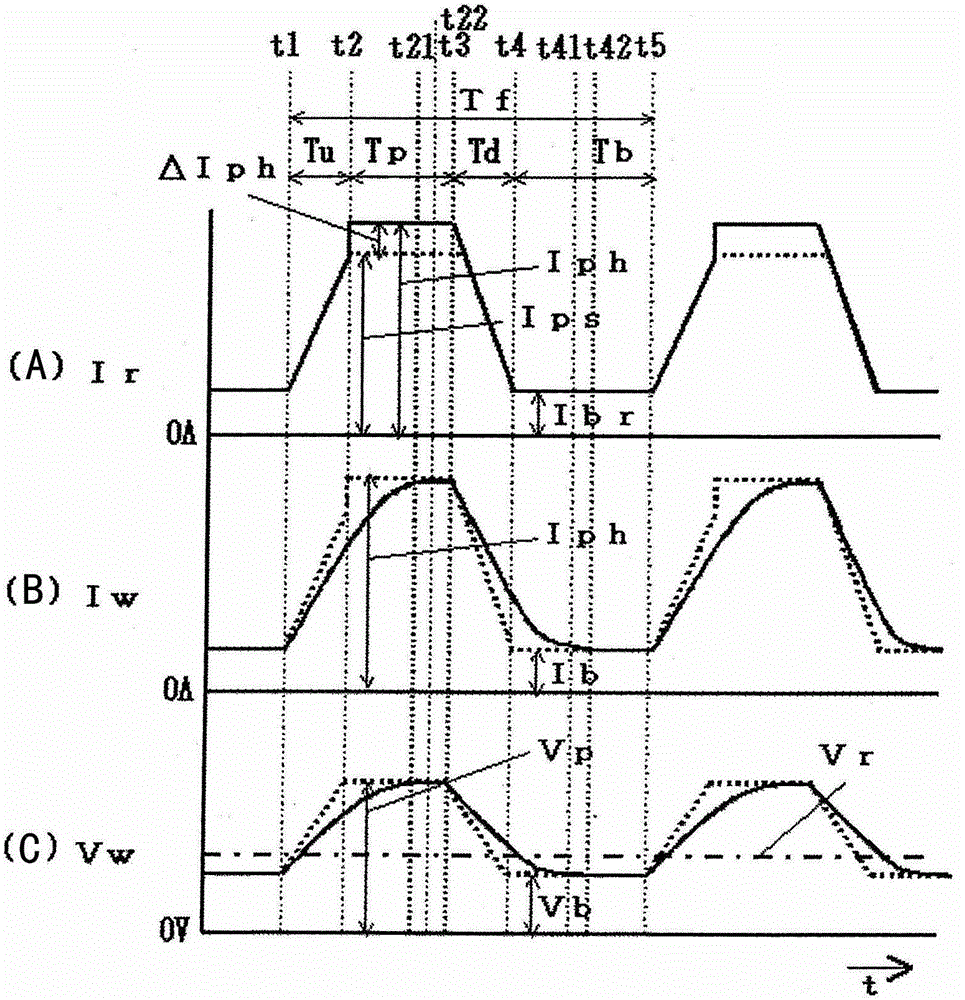
[0081] figure 1 It is a current and voltage waveform diagram showing the pulse arc welding control method according to the embodiment of the present invention when the external inductance value is large. The graph (A) shows the time change of the welding current setting signal Ir, the graph (B) shows the temporal change of the welding current Iw, and the graph (C) shows the temporal change of the welding voltage Vw. Since the external inductance value is large, this figure is a case where the rising speed Bd of the welding current Iw in the peak rising period Tu is lower than the reference speed Bt. This figure corresponds to the above Figure 5 . In this figure, the standard peak current setting Ips vs. Figure 4 as well as Figure 5 The peak current setting value Ipr is the same value. Hereinafter, description will be made with reference to this figure.

[0082...


PUM

PropertyMeasurementUnit
diameteraaaaaaaaaa

Abstract

PROBLEM TO BE SOLVED: To maintain a stable droplet transfer state even when an external inductance value is large in pulse arc welding.SOLUTION: In a pulse arc welding control method, a welding current Iw is applied in such a way as to rise from a base current Ib to a peak current Ip during a peak rising period Tu, become the peak current Ip during a peak period Tp, fall from the peak current Ip to the base current Ib during a peak falling period Td, and become the base current Ib during a base period Tb. A rising rate of the welding current Iw during the peak rising period Tu is detected. When the rising rate is equal to or higher than a reference rate, the peak current Ip is set to a standard peak current value Ips. When the rising rate is lower than the reference rate, the peak current Ip is set to an increased peak current value Iph larger than the standard peak current value Ips. When an external inductance value is large, the peak current Ip is increased, and a pinch force becomes strong, so that a droplet transfer state is stabilized.

Description

technical field [0001] The present invention relates to a pulse arc welding control method capable of stabilizing a droplet transfer state even when an external inductance value due to a welding cable is large. Background technique [0002] Figure 4 It is a general current and voltage waveform diagram of consumable electrode pulsed arc welding. The graph (A) shows the time change of the welding current setting signal Ir, the graph (B) shows the temporal change of the welding current Iw, and the graph (C) shows the temporal change of the welding voltage Vw. The welding current setting signal Ir is a signal for setting the welding current Iw. The welding current Iw is the current of the energized arc, and the welding voltage Vw is the voltage applied between the welding wire and the base metal. Hereinafter, description will be made with reference to this figure. [0003] As shown in (A) of the figure, the welding current setting signal Ir becomes a value rising from the ba...

Claims


Application Information

Patent Timeline
Patent Type & Authority Patents(China)
IPC IPC(8): B23K9/09B23K9/095
CPCB23K9/092B23K9/0732B23K9/093B23K9/095
Inventor 山田浩贵波多晓
Owner DAIHEN CORP
Learn More