Nailing device

A technology for nail drivers and pins, which is applied in the field of nail drivers, and can solve the problems of falling off, reducing the fixing strength, and skewed placement of nails, etc.

Active Publication Date: 2014-02-12
HILTI AG
View PDF8 Cites 3 Cited by
  • Summary
  • Abstract
  • Description
  • Claims
  • Application Information

AI Technical Summary

Problems solved by technology

The following problems may occur in this way: According to the disadvantageous processing mode, the nail driver can be tilted sideways during the setting of the nail, so that the nail is set in a

Method used


Image

  • Nailing device
  • Nailing device
  • Nailing device

Examples


Embodiment Construction

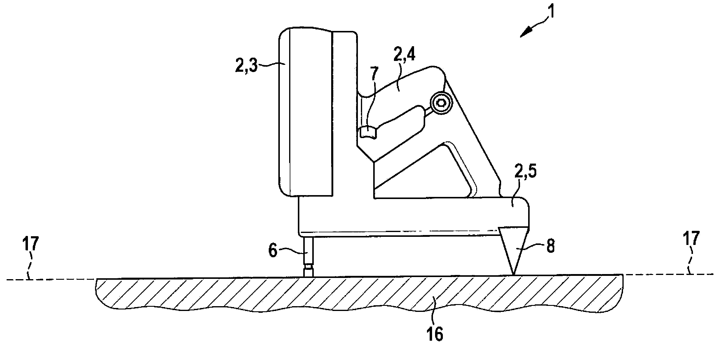
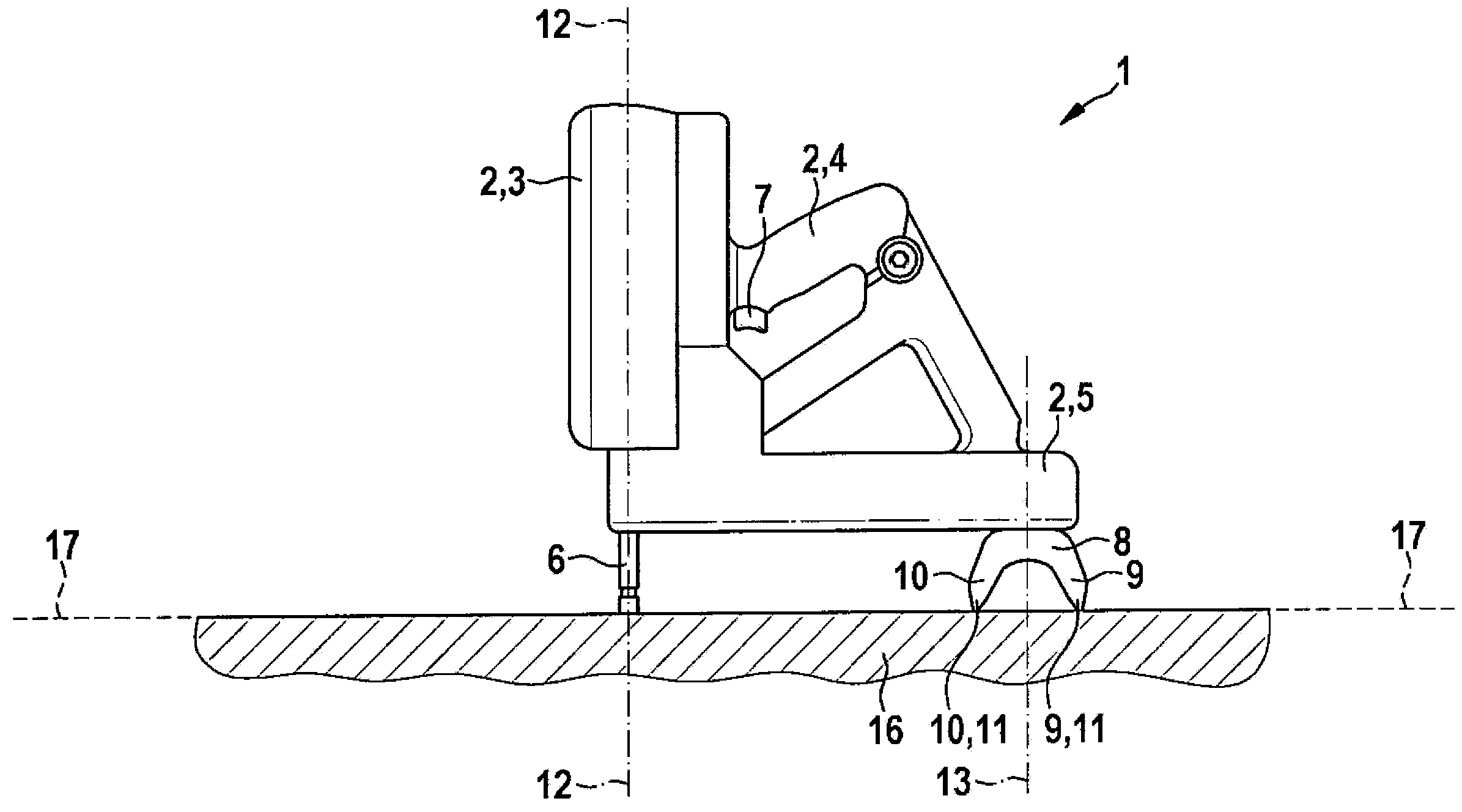
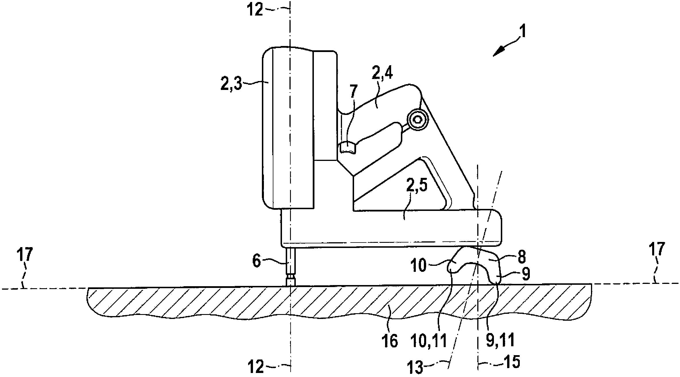
[0036] The nail driver 1 is used to drive nails (not shown) into an object 16 or a substrate 16 made of wood, concrete or steel, for example. To this end, the nail driver 1 has a housing 2 made of metal and / or plastic, which is usually in the form of multiple parts. Here, inside the nail driver body 3 surrounded by the casing 2 is a mounting mechanism not shown in the figure, and the mounting mechanism is operated in an electric, pneumatic or combustion technology manner. Surrounded by another part of the housing 2 is a nail magazine 5. The nail box 5 contains a large number of nails. In order to install the nails, the nails must be transported from the nail box 5 to the placement mechanism, and the placement mechanism is used to electrically or pneumatically drive the nails through a pin guide element 6 as a component of the placement mechanism. Hit into object 16. The pin guide element 6 here has a longitudinal axis 12, and the setting mechanism can be activated with a trig...


PUM


Abstract

A nailing device (1), comprising a housing (2), a nail cartridge (5), a setting mechanism for the setting of the nails, a bolt guiding element (6) for placement on the object (16) into which the nails are to be introduced, so that the bolt guiding element (6) is used for the setting of the nails and for the support for the nailing device, a trigger (7) for the activation of the setting mechanism, a supporting foot (8) for the additional support of the nailing device (1); it should be possible to drive the nails into the object (16) without a special alignment of the nailing device (1) by the operator, essentially vertically relative to a hypothetical object plane (17) spanned by the surface of the object (16) into which the nails are driven. This goal is attained in that the supporting foot (8) is provided with two supporting elements (9, 10) for a two-point contact, so that the nailing device (1) together with the bolt guiding element (6) has a three-point contact. Fig. 2 ---- ------ ------------------ ...... .....

Description

Technical field [0001] The invention relates to a nail driver. Background technique [0002] Nail drivers are especially used in the construction industry to place nails (spikes) or staples into objects or substrates, such as objects or substrates made of wood, concrete, or steel. In this way, a larger number of nails or staples can be inserted into the object or the substrate in a shorter time than in the case of manually hammering nails into the object using a hammer. Among them, the nail driver is usually driven by pneumatic, electric or combustion technology. The nail magazine is used to store a larger number of nails or staples. [0003] DE19508437C2 discloses a pneumatic nail driver, and DE8907788U1 discloses an electric nail driver. DE3151658A1 introduces a placement appliance that runs on gas power. [0004] Here, the nail should be as perpendicular as possible to an imaginary object plane formed by the surface of the object or substrate and be driven into the object or s...

Claims


Application Information

Patent Timeline
IPC IPC(8): B25C1/04B25C1/06B25C3/00
CPCB25H1/0021B25C3/00B25C1/00B25C7/00
Inventor M·格拉奇奥利K·弗朗茨K·里克斯
Owner HILTI AG
Why Eureka
Try Eureka