An injection shaft support connection device

A connection device and shaft support technology, applied in the field of injection molding, can solve the problems of weak structure, short service life, unreliability, etc., and achieve the effect of avoiding the leakage of lubricating oil and the entry of dust

Inactive Publication Date: 2016-04-27
ZHEJIANG UNIV
View PDF4 Cites 0 Cited by
  • Summary
  • Abstract
  • Description
  • Claims
  • Application Information

AI Technical Summary

Problems solved by technology

[0004] The purpose of the present invention is to address the above problems, to provide a support connection device for injection shaft; to solve the technical problems existing in the prior art, such as weak structure, unreliable, short service life and so on.

Method used


Image

  • An injection shaft support connection device
  • An injection shaft support connection device
  • An injection shaft support connection device

Examples


Embodiment Construction

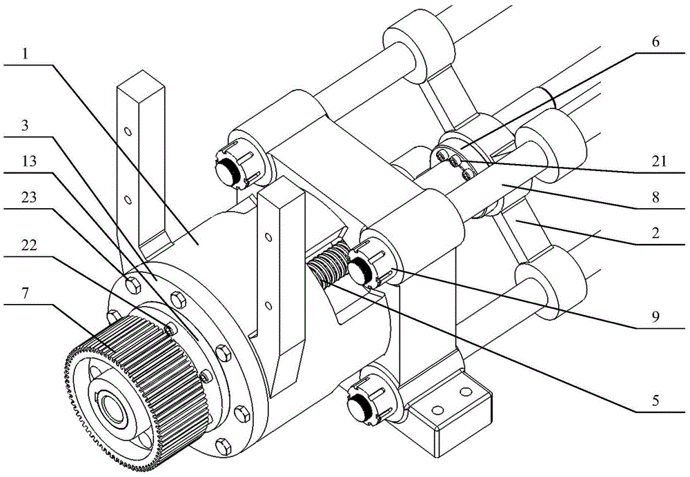
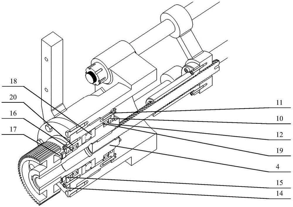
[0021] Such as Figure 1-6 As shown, an injection shaft support connection device includes an injection table 1, the injection table 1 has an inner cavity 1f, a bearing seat 3 is inserted into the inner cavity 1f and is fixedly connected with the injection table 1, and the bearing seat 3 is provided with The injection shaft 4 that is rollingly connected with the bearing seat 3 has an injection shaft center hole 4a, one end of the injection shaft 4 is fixedly connected to the injection pulley 7, and the other end is fixedly connected to the ball screw through the injection shaft center hole 4a 5. The ball screw 5 is screwed to the injection thrust frame 2, and the ball nut 6 is sleeved on the ball screw 5, and the ball nut 6 is fixedly connected to the injection thrust frame 2.

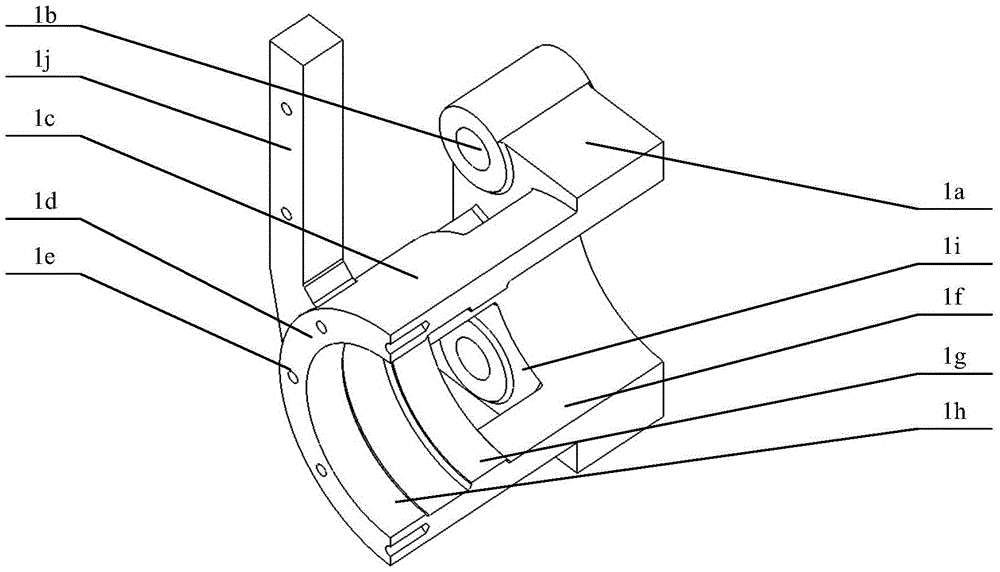
[0022] One end of the injection platform 1 is a square plate 1a, and the other end is a cylinder 1c. The four corners of the square plate 1a are provided with guide rod holes 1b, and the cylinder 1c is...


PUM


Abstract

The invention discloses an injection shaft support connecting device which solves the technical problems of non-firm and non-reliable structure, short service life and the like of the prior art. The injection shaft support connecting device comprises an injection platform which is provided with an inner cavity, a bearing base is inserted in the inner cavity and is fixedly connected with the injection platform, an injection shaft, which is connected with the bearing base in a rolling manner, is arranged in the bearing base, and is provided with an injection shaft center hole, an injection belt wheel is fixedly connected to one end of the injection shaft, the other end of the injection shaft is fixedly connected with a ball screw after passing through the injection shaft center hole, the ball screw is connected with an injection thrust frame, and a ball nut is arranged on the ball screw in a sleeved manner, and is fixedly connected with the injection thrust frame. The injection shaft support connecting device provided by the invention is capable of ensuring that an injection machine realizes an injection function, and enables the injection machine to have firm and stable properties for a long time.

Description

technical field [0001] The invention belongs to the technical field of injection molding, and relates to an injection molding machine, in particular to an injection shaft supporting connection device. Background technique [0002] In the injection stage of the working process, the injection screw needs to move forward and backward along the axis. When pushing forward, the screw does not rotate, and a huge forward thrust needs to be applied to the screw. This linear movement and force are transmitted through the injection shaft, and the injection shaft will be subjected to torque and radial force at the same time during the working process. The plasticizing parts of the injection molding machine driven by the servo motor need to convert the rotary motion into a linear motion. High-quality injection molding machines also require flexible rotation of the injection shaft, stable and firm support, and high transmission efficiency. [0003] The supporting connection of the injec...

Claims


Application Information

Patent Timeline
Patent Type & Authority Patents(China)
IPC IPC(8): B29C45/58
CPCB29C45/5008B29C2045/5052
Inventor 李凌丰陈豪管灵波张振然
Owner ZHEJIANG UNIV
Why Eureka
Try Eureka