Electronic component carrying device and electronic component testing device
A technology of electronic components and handling devices, which is applied to measuring devices, transportation and packaging, computer parts, etc., and can solve problems such as inability to obtain inspection results
- Summary
- Abstract
- Description
- Claims
- Application Information
AI Technical Summary
Problems solved by technology
Method used
Image
Examples
no. 1 approach
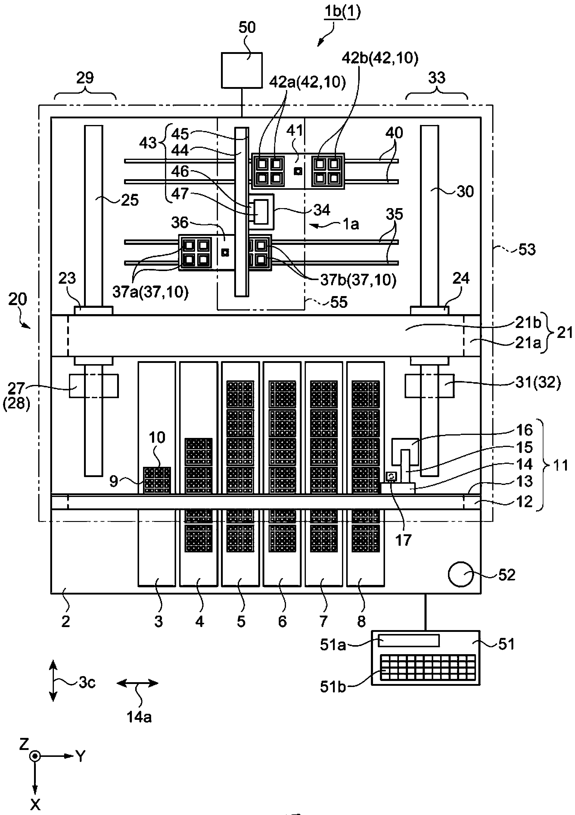
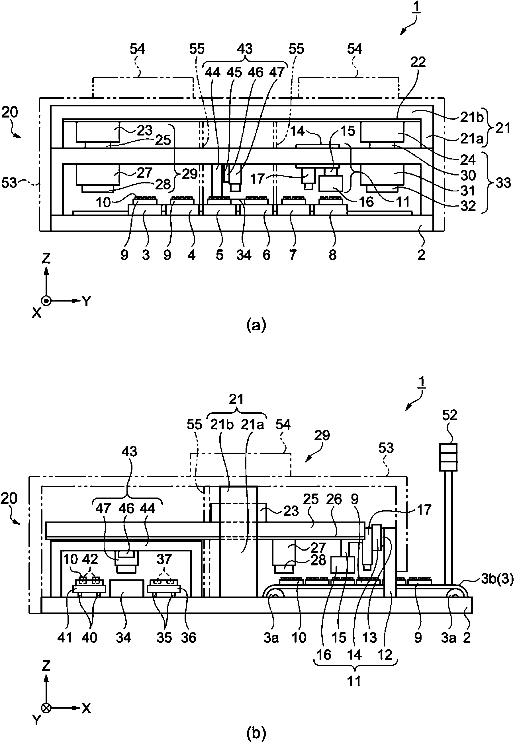
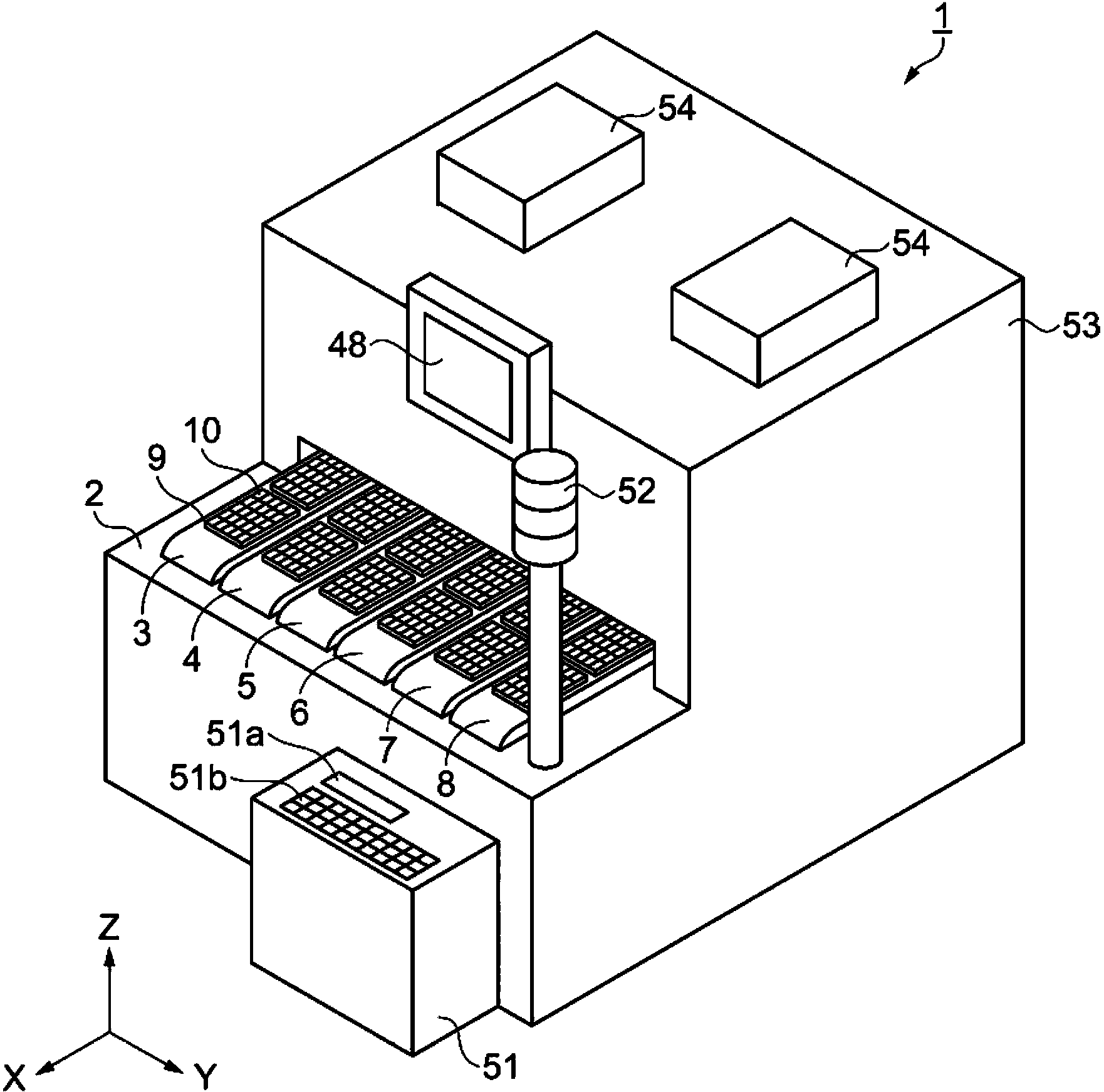
[0055] according to Figure 1 to Figure 8 The component inspection device according to the first embodiment will be described.
[0056] Component inspection device
[0057] figure 1 It is a schematic plan view showing the structure of the component inspection device, and is a view with a cover removed. figure 2 (a) and figure 2 (b) is a schematic side view showing the configuration of the component inspection device. image 3 It is a schematic perspective view showing the structure of the component inspection device. Such as Figure 1 ~ Figure 3 As shown, the component inspection device 1 has a rectangular plate-shaped base 2 . The directions in which the two sides perpendicular to the base 2 in the plan view of the base 2 extend are defined as the X direction and the Y direction, and the vertical direction is defined as the −Z direction. The component inspection device 1 is mainly composed of an inspection unit 1a that inspects electronic components, and a transport ...
no. 2 approach
[0143] Next, use Figure 9 One embodiment of an electronic component having an individual identification number and a component inspection device will be described. Figure 9 (a) is a schematic plan view for explaining electronic components, Figure 9 (b) is a schematic side view showing the structure of the component inspection device. This embodiment differs from the first embodiment in that a barcode is used for displaying the product name 10b and the individual identification number 10c. In addition, description of the same points as those of the first embodiment will be omitted.
[0144] That is, in this embodiment, if Figure 9 As shown in (a), a character string indicating a manufacturer name 85 a , a product name 85 b , and an individual identification number 85 c is printed on the electronic component 85 . In addition, an item barcode 85d indicating the product name 85b as a barcode and an individual identification barcode 85e as identification information indicat...
Deformed example 1
[0151] In the above-mentioned second embodiment, the one-dimensional individual identification barcode 85e is printed on the electronic component 85 . Barcodes are not limited to one-dimensional, but can also be two-dimensional barcodes. Figure 10 It is a schematic top view for explaining an electronic component. Such as Figure 10 As shown, a character string indicating a manufacturer name 88a, a product name 88b, and an individual identification number 88c is printed on the electronic component 88 . In addition, an item barcode 88d representing a product name 88b in a two-dimensional barcode and an individual identification barcode 88e as identification information representing an individual identification number 88c in a two-dimensional barcode are printed on the electronic component 88 .
[0152] Furthermore, the barcode reader 87 is a device that converts a two-dimensional barcode into character data. By changing the barcode from one-dimensional to two-dimensional, th...
PUM
 Abstract
Description
Claims
Application Information
 - R&D
- Intellectual Property
- Life Sciences
- Materials
- Tech Scout
- Unparalleled Data Quality
- Higher Quality Content
- 60% Fewer Hallucinations
Browse by: Latest US Patents, China's latest patents, Technical Efficacy Thesaurus, Application Domain, Technology Topic, Popular Technical Reports.
© 2025 PatSnap. All rights reserved.Legal|Privacy policy|Modern Slavery Act Transparency Statement|Sitemap|About US| Contact US: help@patsnap.com


