Debugging System, Debugging Method, and Program

a debugging system and debugging method technology, applied in the field of debugging system and debugging method, can solve the problems of raising the cost of the system, requiring special requirements for equipment whose components are built-in, and mounting dedicated hardwar

Inactive Publication Date: 2009-09-17
NEC CORP
View PDF13 Cites 8 Cited by
  • Summary
  • Abstract
  • Description
  • Claims
  • Application Information

AI Technical Summary

Benefits of technology

[0056]As described in the foregoing explanation, the provision of a debugging program activation instruction distribution means and debugging program activation means in the present invention can realize a configuration that enables the activation of a debugging program in any execution unit and at any timing, and the invention can therefore obtain the effect of causing the generation of a fault in a state in which only the normal operation program is being executed, or can proceed with operations until immediately before the generation of the fault and then activate a debugging program in the execution unit that carries out the process that causes the fault to occur and then implement the task of debugging.

Problems solved by technology

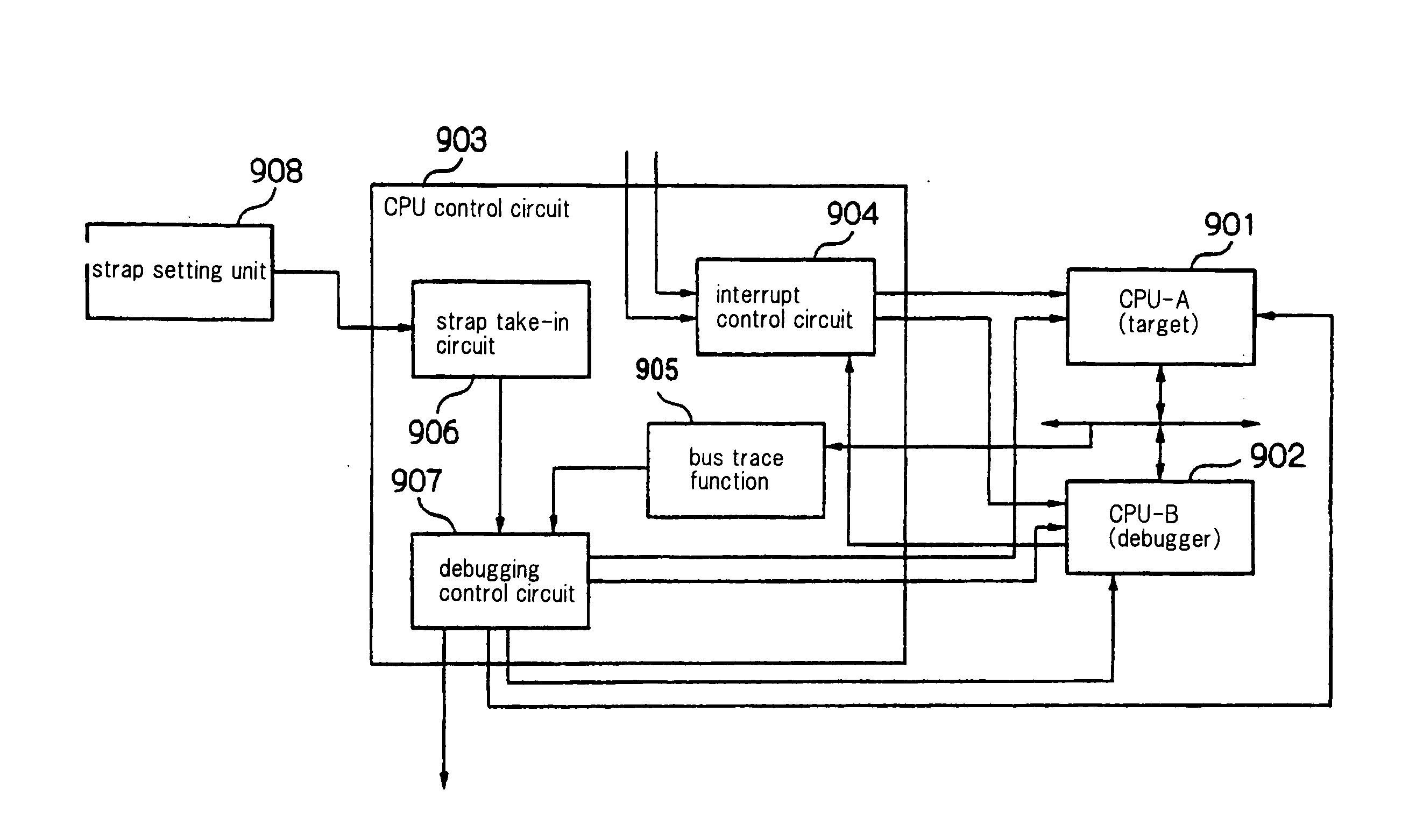
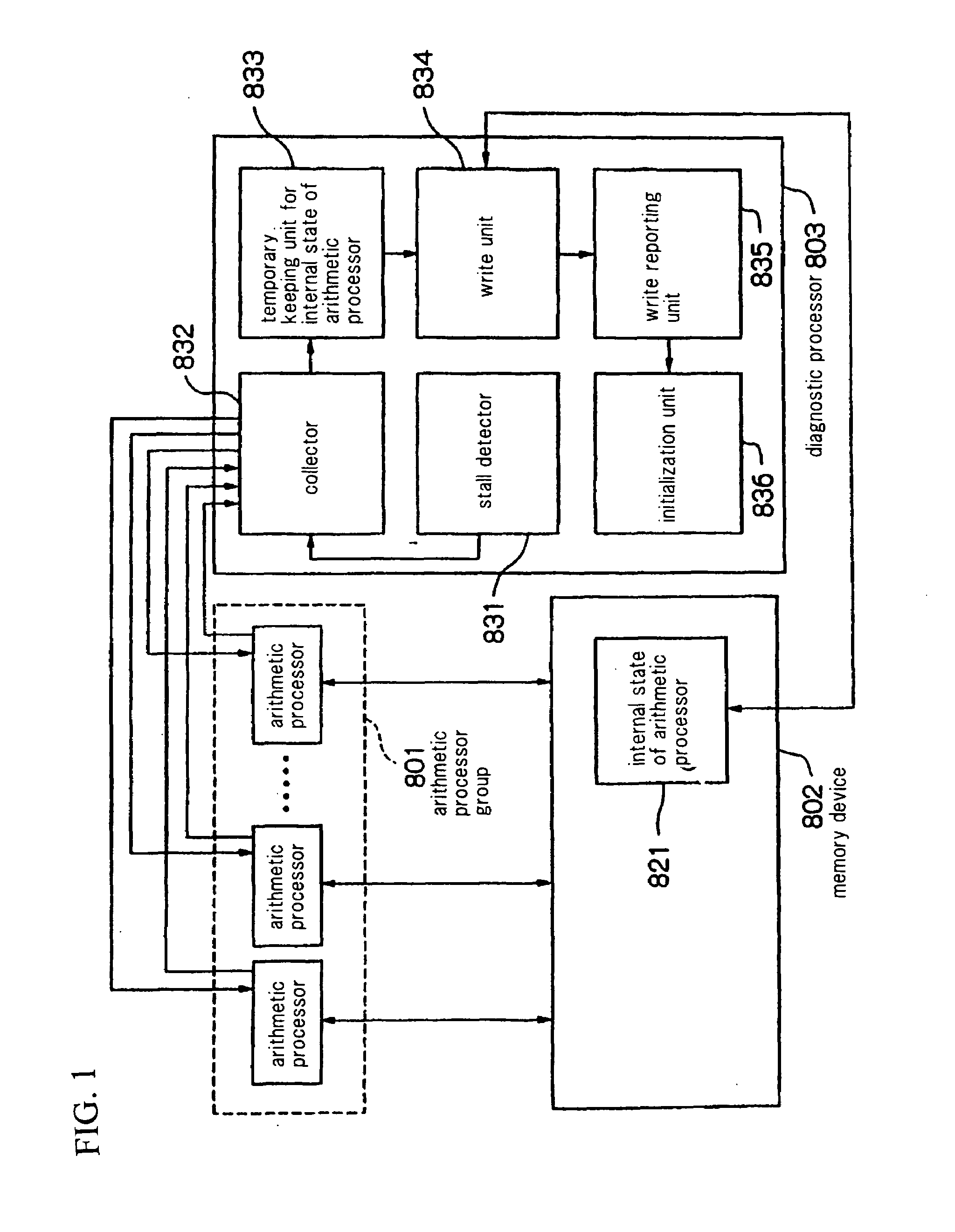
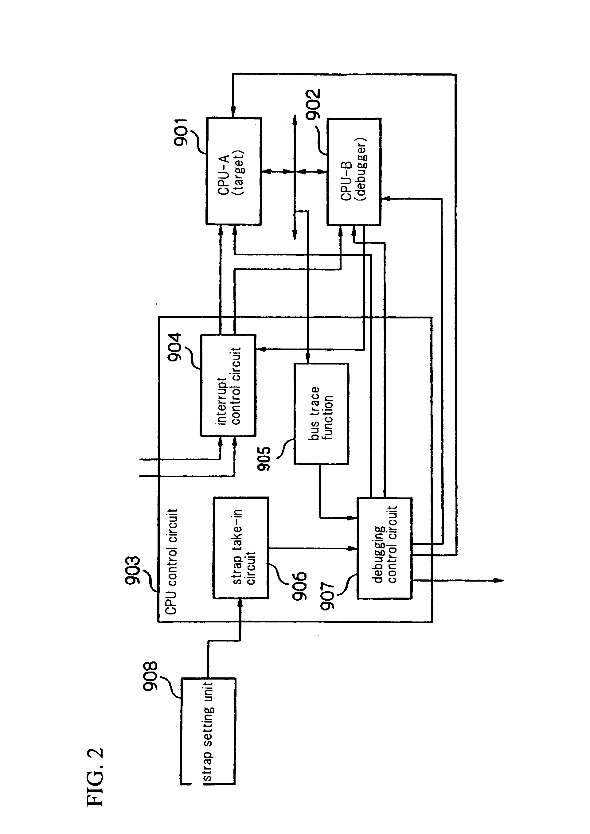
Although a method in which diagnostic processor 803, which is high-function dedicated hardware for debugging, is mounted in a system as in the related art described in Patent Document 1 can achieve the effect of raising the efficiency of debugging, this method also has the drawbacks of requiring the addition of hardware that does not contribute to normal operations and further, of raising the cost of the system.
In addition, requirements that mean increased cost for equipments whose components are built-in are particularly severe, and this frequently prohibits the mounting of dedicated hardware.
In this method, however, the cause of the occurrence of a fault cannot be adequately investigated in many cases.
However, putting these debugging programs into operation beforehand increases the load on the CPU, and further, because the debugging programs use storage area, influences the operation timing of the normal operation program.
As a result, the existence of the debugging program has the drawbacks of preventing the occurrence of faults that may occur in normal operation, and conversely, of causing the occurrence of faults that should not occur when executing only the normal operation program.
Further, in a program that is executed in a system in which a plurality of execution units perform linked operation, the execution unit in which a fault, particularly a fault produced by timing, occurs cannot be uniquely determined, and the occurrence of such a fault is therefore difficult to anticipate.
When an execution unit enters a stalled state or when a fault occurs that has an effect on the operation of execution units, the debugging program may be unusable on the execution unit that is in a stalled state, or the debugging program may be unusable in execution units in which the operation is affected.
However, when the site of the fault occurrence cannot be uniquely determined, an execution unit that is unaffected by the fault also cannot be determined.
As a result, when a fault occurs that has an effect upon the operation of a debugging CPU that has been assigned at the time of resetting, the state cannot be debugged.

Method used


Image

  • Debugging System, Debugging Method, and Program
  • Debugging System, Debugging Method, and Program
  • Debugging System, Debugging Method, and Program

Examples


first exemplary embodiment

[0081]Explanation first regards the debugging system of the first exemplary embodiment of the present invention with reference to the accompanying figures.

[0082]As shown in FIG. 4, the debugging system of the present exemplary embodiment is provided with: two execution units A and B, communication port 1, rewriteable memory unit 2 such as RAM (Random Access Memory), and program storage unit 3 composed of, for example, an HDD (Hard Disk Drive) and in which various programs are stored. The memory areas of memory unit 2 are made up from execution unit-A program area 6 and execution unit-B program area 7.

[0083]As shown in FIG. 5, execution unit-A program area 6 is provided with: debugging program activation instruction distribution unit (represented as “distribution unit” in FIG. 5) 61, debugging program activation unit (represented as “activation unit” in FIG. 5) 62, debugging program 63, and normal operation program 64. These components are provided as programs that are executed on ex...

second exemplary embodiment

[0111]Explanation next regards the debugging system of the second exemplary embodiment of the present invention with reference to the accompanying figures.

[0112]The first exemplary embodiment described in the foregoing explanation was a case in which the present invention was applied to a system in which the execution unit that is the object of communication of a communication port can be changed. However, depending on the system, there are some systems in which the execution unit that is the object of communication of a communication port cannot be changed, i.e., in which the execution unit that is the communication object of a communication port is fixed. When the present invention is applied to this type of system, a command cannot be transmitted to a debugging program that has been activated on an execution unit that is not the communication object of a communication port, even when a debugging program activation instruction distribution unit is provided for each execution unit....

third exemplary embodiment

[0122]Explanation next regards the debugging system of the third exemplary embodiment of the present invention with reference to the accompanying figures.

[0123]As with the debugging system of the first exemplary embodiment, the debugging system of the present exemplary embodiment is a system in which the present invention is applied to a system that allows change of the execution unit that is the object of communication of a communication port.

[0124]In a system that allows change of the execution unit that is the object of communication of a communication port, commands to a debugging program can be transmitted by switching the communication ports. However, when a plurality of debugging programs are placed in operation at the same time, problems can be expected to arise in switching the communication ports. In addition, a certain amount of overhead is required for the process of changing the execution unit that is the object of a communication of communication port.

[0125]As a result...


PUM


Abstract

Upon receiving debugging program activation instructions sent from a communication port (1), debugging program activation instruction distribution units (61 and 71) distribute the received debugging program activation instructions to execution units designated by these activation instructions. Debugging program activation units (62 and 72) are provided for each execution unit (A and B) and, based on the activation instructions distributed by the activation instruction distribution units (61 and 71), activate debugging programs (63 and 73) on the execution units designated by these activation instructions.

Description

TECHNICAL FIELD[0001]The present invention relates to a debugging system, a debugging method, and a program, and more particularly relates to a debugging system, a debugging method, and a program in a system having a plurality of execution units.BACKGROUND ART[0002]Recent years have witnessed marked growth in the scale of programs being developed, and the time required for the task of debugging is having an increasing impact on product development schedules. As a result, there is a need for the construction of an environment that would allow debugging to be carried out with greater efficiency. A method in which a diagnostic processor is used to support debugging such as the debugging system described in Patent Document 1 “Processor Information Collector and Program Recording Medium Therefor” is one method of efficiently carrying out debugging.[0003]As shown in FIG. 1, this debugging system of the related art is provided with arithmetic processor group 801, memory device 802, and dia...

Claims


Application Information

Patent Timeline
Patent Type & Authority Applications(United States)
IPC IPC(8): G06F11/36G06F9/44
CPCG06F11/366G06F11/3632G06F11/28G06F11/36
Inventor SUZUKI, NORIAKISAKAI, JUNJI
Owner NEC CORP
Why Eureka
Try Eureka