

A pilot frequency measurement method and device
A pilot frequency measurement and pilot signal technology, applied in pilot signal allocation, baseband system components, wireless communication, etc., can solve problems such as pilot frequency configuration, improve system spectrum efficiency, avoid serious resource occupation, and avoid pilot The effect of frequent overhead
- Summary
- Abstract
- Description
- Claims
- Application Information
AI Technical Summary
Problems solved by technology
Method used
Image


Examples
Embodiment 1
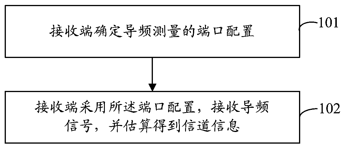
[0089] In this embodiment, the process of pilot frequency measurement may specifically include the following steps:
[0090]Step 1: The network side determines the port configuration of the pilot frequency measurement and the time domain configuration of the corresponding port configuration, and notifies the corresponding port configuration information and time domain configuration information to the receiving end;
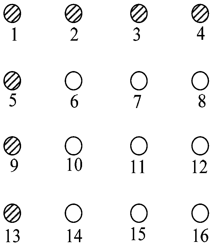
[0091] Specifically, in this embodiment, it is determined to use such as figure 2 In the port configuration shown, there are 16 ports in total, and the 7 ports (ports 1, 2, 3, 4, 5, 9, 13) in the shaded part are ports for sending pilot signals, and the 9 ports in the non-shaded part ports (ports 6, 7, 8, 10, 11, 12, 14, 15, and 16) are ports that do not transmit pilot signals. That is to say, in this embodiment, the first row port and the first column port are used to send pilot information.
[0092] The port configuration information of the above port configur...
Embodiment 2
[0103] In this embodiment, the process of pilot frequency measurement may specifically include the following steps:
[0104] Step 1: The network side determines the port configuration of the pilot frequency measurement and the time domain configuration of the corresponding port configuration, and notifies the corresponding port configuration information and time domain configuration information to the receiving end;
[0105] Specifically, in this embodiment, it is determined to use such as Figure 4 In the port configuration shown, there are 16 ports in total, and the 10 ports in the shaded part (ports 1, 2, 3, 4, 5, 8, 9, 12, 13, 16) are ports for sending pilot signals , the 6 ports (ports 6, 7, 10, 11, 14, and 15) in the non-shaded part are ports that do not send pilot signals. That is to say, in this embodiment, the ports in the first row, the ports in the first column, and the ports in the fourth column are used to send pilot information.
[0106] In this embodiment, an ...
Embodiment 3
[0115] In this embodiment, the process of pilot frequency measurement may specifically include the following steps:
[0116] Step 1: The transmitting end determines the port configuration and time domain configuration of the pilot measurement according to the preset port configuration. Since the port configuration information is preset, there is no need to notify the receiving end of signaling. The transmitting end only needs to send the time domain configuration information notify the receiver;
[0117] Specifically, in this embodiment, it is determined to use such as Figure 5 shown in the port configuration, Figure 5 There are four kinds of port configurations, the first port configuration is the same as figure 1 The same, that is, the ports in the first row (ports 1, 2, 3, 4) and the ports in the first column (ports 1, 5, 9, 13) are used to send pilot information; the second port is configured to use the second column The ports (ports 2, 6, 10, 14) and the ports in the...
PUM
 Abstract
Description
Claims
Application Information