Assembling tool of aircraft wing box C-shaped beam and detecting and correcting method of assembling tool

A technology for assembling tooling and wings, which is applied in metal processing, manufacturing tools, workpiece clamping devices, etc., can solve the problems of inability to protect the angle deviation of the C-shaped beam, meet the design requirements, and affect the performance of materials, etc. The effect of inspection and assembly cycle, improvement of production efficiency and quality, and simple and easy operation

Inactive Publication Date: 2014-02-19
SHANGHAI JIAO TONG UNIV
View PDF4 Cites 11 Cited by
  • Summary
  • Abstract
  • Description
  • Claims
  • Application Information

AI Technical Summary

Problems solved by technology

Composite C-shaped beams will shrink during the demoulding process after preparation, often easily causing the angle between the wing plate and the web plate to be less than the pre-designed 90 degrees, resulting in manufacturing errors
At the same time, due to the brittleness of carbon fiber composite materials, if the angle between the wing plate and the web is forcibly corrected, it will easily cause material damage and affect material performance.
Therefore, there are three forms of expression for the prepared C-shaped beam during assembly: the first is that the included angle directly meets the technical requirements, and can be directly processed by machining such as trimming; the second is that a certain force is allowed to be applied to make the included angle If it can meet the design requirements, it can be considered as meeting the technical requirements; the third type is that even if a certain force is applied, the included angle cannot meet the design requirements, and the assembly process cannot be carried out.
[0003] At present, the traditional tooling fixtures cannot well correct the angle deviation of the C-beam and in the process cannot better protect the damage caused by the brittleness of the C-beam, and cannot better meet the needs of modern aircraft. Low-cost, high-quality requirements of the manufacturing industry

Method used


Image

  • Assembling tool of aircraft wing box C-shaped beam and detecting and correcting method of assembling tool
  • Assembling tool of aircraft wing box C-shaped beam and detecting and correcting method of assembling tool
  • Assembling tool of aircraft wing box C-shaped beam and detecting and correcting method of assembling tool

Examples


Embodiment Construction

[0032] The embodiments of the present invention are described in detail below: This embodiment is implemented on the premise of the technical solution of the present invention, and provides detailed implementation modes and specific operation processes. It should be pointed out that for those skilled in the art, without departing from the concept of the present invention, several modifications and improvements can be made, which all belong to the protection scope of the present invention.

[0033] see also Figure 1 to Figure 8 .

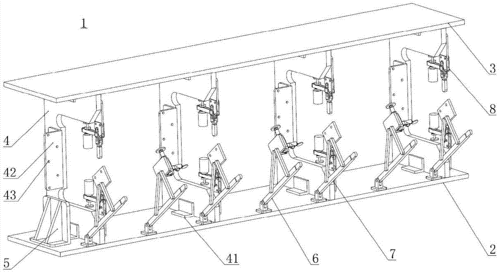
[0034] According to an aspect of the present embodiment, an assembly tool for a C-beam of an aircraft wing box is provided, including a base platform and a top platform, the base platform and the top platform are both rectangular structures, the same size, and opposite positions; define the The length direction of the base platform is vertical, the width direction is horizontal, and the direction perpendicular to the base platform is vertical; ther...


PUM


Abstract

The invention provides an assembling tool of an aircraft wing box C-shaped beam. The assembling tool comprises a rectangular base platform and a rectangular top platform which are the same in size and opposite in position. A vertical positioning device is disposed between the base platform and the top platform. A transverse positioning device and a vertical clamping and included angle correcting device using magnetic transmission are fixedly connected to the vertical. A longitudinal positioning device is disposed at the edge, close to the width, of the base platform. A transverse clamping device and a corner piece assembling device are disposed at the lateral edge in the length direction of the base platform. The invention further provides a detecting and correcting method of the assembling tool. The assembling tool and the detecting and correcting method have the advantages that cycle of quality inspection and assembling is shortened, cost is saved, and production efficiency and quality are improved; an overload protection function is provided, simple operation and practicality are achieved, and detection, correction and assembling can be completed fast.

Description

technical field [0001] The invention relates to the technical field of aircraft manufacturing and assembly, in particular to an assembly tool and a detection and correction method for a C-shaped beam of an aircraft wing box. Background technique [0002] The manufacture of composite C-beams of aircraft wing boxes is an important part of the manufacture of large aircraft wings. Composite materials are widely used in aircraft due to their small specific gravity, large specific strength and specific modulus. The composite C-shaped beam will shrink during the demoulding process after preparation, which often easily causes the angle between the wing plate and the web plate to be less than the pre-designed 90 degrees, resulting in manufacturing errors. At the same time, due to the brittleness of carbon fiber composite materials, if the angle between the wing plate and the web plate is forcibly corrected, it is easy to cause material damage and affect the material performance. Th...

Claims


Application Information

Patent Timeline
Patent Type & Authority Applications(China)
IPC IPC(8): B25B11/02B25B27/00
CPCB23P19/006B23P19/10
Inventor 王华司索
Owner SHANGHAI JIAO TONG UNIV
Why Eureka
Try Eureka