Cylindrical clamping barrel

A cylindrical and cartridge technology, applied in the field of cylindrical cartridges, can solve the problems of easily damaged gear shafts and inconvenient storage of gear shafts, and achieve the effect of preventing rotation

Inactive Publication Date: 2014-02-19
唐山宝龙钢铁有限公司
View PDF6 Cites 2 Cited by
  • Summary
  • Abstract
  • Description
  • Claims
  • Application Information

AI Technical Summary

Problems solved by technology

But the existing gear shaft is inconvenient to store, if it is not well preserved, it is very easy to damage the gear shaft

Method used


Image

  • Cylindrical clamping barrel
  • Cylindrical clamping barrel

Examples


Embodiment Construction

[0017] The preferred embodiments of the present invention will be described in detail below in conjunction with the accompanying drawings, so that the advantages and features of the present invention can be more easily understood by those skilled in the art, so as to define the protection scope of the present invention more clearly.

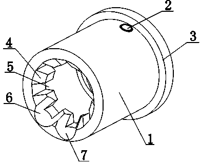
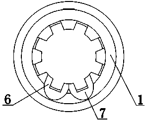
[0018] like Figure 1 to Figure 2 As shown, a cylindrical cartridge includes a cylinder body 1, an insertion column 2 is provided on the outer surface of the cylinder body 1, a plurality of protruding teeth 4 are arranged on the inner surface of the end of the cylinder body 1, and several protruding teeth 4 are arranged In a circular shape, there is a card slot 5 between two adjacent protruding teeth 4. The end of the cylinder 1 is provided with a first inclined chute 6 and a second inclined chute 7. The cross section of the first inclined chute 6 It is U-shaped, the cross section of the second inclined chute 7 is U-shaped, the first inclined chu...


PUM


Abstract

The invention discloses a cylindrical clamping barrel which comprises a barrel body. An inserting column is arranged on the outer surface of the barrel body, a plurality of protruding teeth are arranged on the inner surface of the end portion of the barrel body, the protruding teeth are arranged to be in a circular shape, claming grooves are formed between adjacent protruding teeth, a first inclined sliding groove and a second inclined sliding groove are formed in the end portion of the barrel body, the cross section of the first inclined sliding groove is in a U-type shape, the cross section of the second inclined sliding groove is in a U-type shape, the first inclined sliding groove is arranged between two adjacent protruding teeth, and the second inclined sliding groove is arranged between two adjacent protruding teeth. According to the cylindrical clamping barrel, a gear shaft can be sleeved quickly, the gear shaft will not be damaged through the inclined sliding grooves, and the gear shaft is clamped more firmly by arranging the protruding teeth and the clamping grooves in a staggered mode.

Description

technical field [0001] The invention relates to a cartridge, in particular to a cylindrical cartridge. Background technique [0002] In the prior art, there are some gears, which often include structures such as shaft bodies, connecting rods, through holes and gears. But existing gear shaft is inconvenient to preserve, if preservation is not good, this gear shaft is very easily damaged. Contents of the invention [0003] The present invention mainly solves the technical problems existing in the prior art, thereby providing a cylinder that can quickly fit the gear shaft, does not damage the gear shaft through the inclined chute, and clamps the gear shaft more firmly through the staggered arrangement of convex teeth and slots cartridge. [0004] Above-mentioned technical problem of the present invention is mainly solved by following technical scheme: [0005] A cylindrical card cartridge, comprising a cylinder body, the outer surface of the cylinder body is provided with...

Claims


Application Information

Patent Timeline
Patent Type & Authority Applications(China)
IPC IPC(8): B65D59/04
Inventor 汤坤
Owner 唐山宝龙钢铁有限公司
Why Eureka
Try Eureka