Tension Control Device

A tension control and resistance device technology, applied in the directions of transportation and packaging, winding strips, thin material processing, etc., can solve the problems of uneven dyeing, discount of dyeing effect, etc., to achieve the effect of tightness

Active Publication Date: 2016-06-15
CHENGDU ROCK SOLID AUTOMATION TECH
View PDF11 Cites 0 Cited by
  • Summary
  • Abstract
  • Description
  • Claims
  • Application Information

AI Technical Summary

Problems solved by technology

In this way, the inner layer and the outer layer of the rolled tape are of the same degree of tightness, which makes the dyeing process uneven in the subsequent dyeing process, and the dyeing effect is greatly reduced.

Method used


Image

  • Tension Control Device
  • Tension Control Device
  • Tension Control Device

Examples


Embodiment

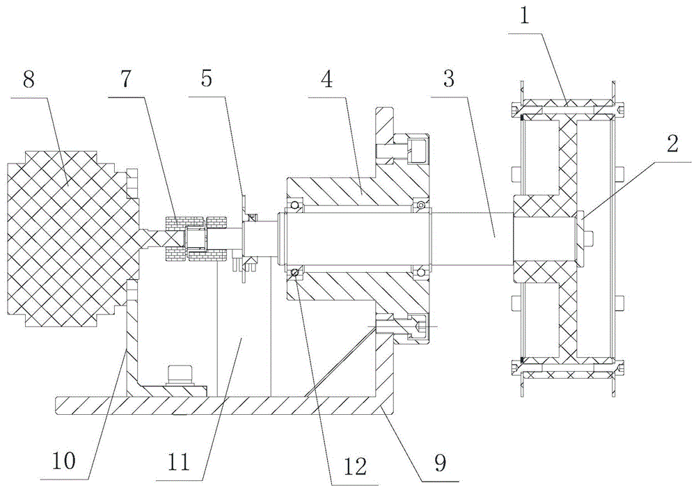
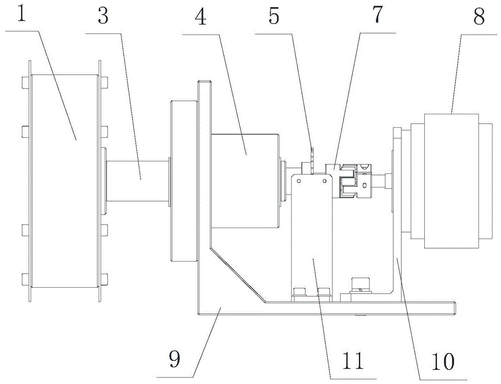
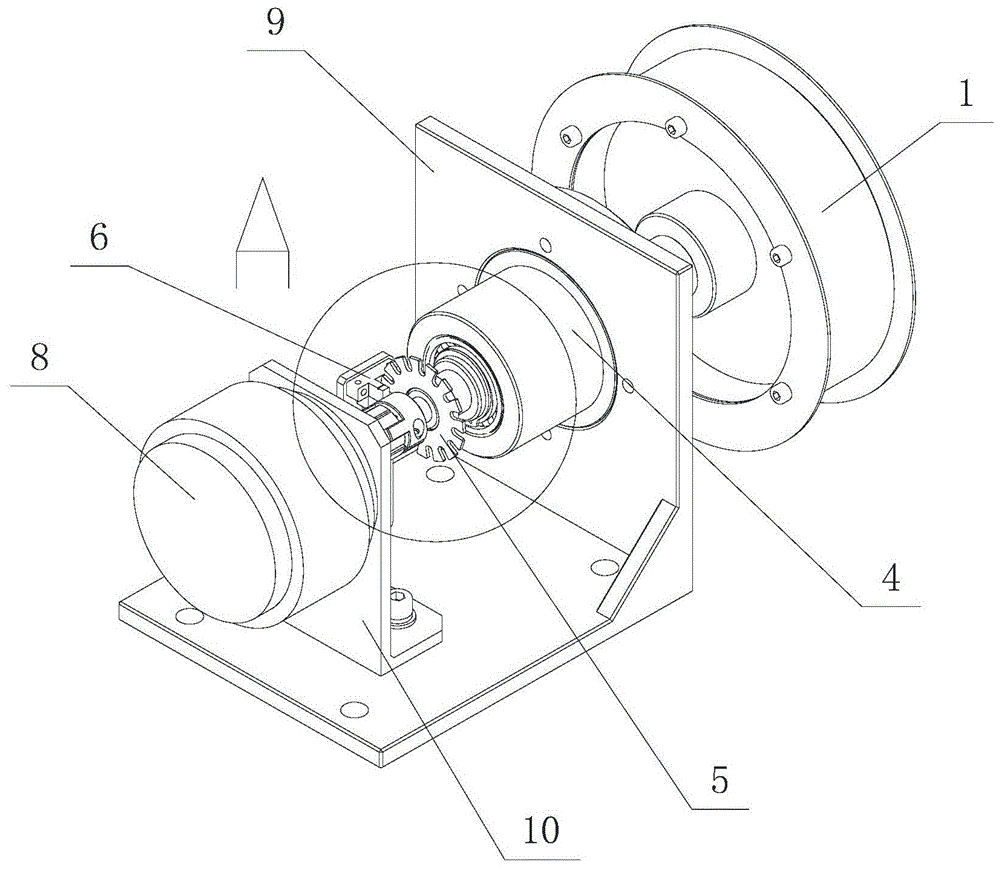
[0020] Example: see figure 1 , figure 2 , image 3 and Figure 4 , a tension control device, including a pulley 1 that passes through the belt, and a rotating shaft 3 that fixes the pulley 1, and is also provided with a length measurement device and a resistance device, and the length measurement device and the resistance device are both connected to the electrical equipment of the equipment The control box is connected, and the outer edge surface of the belt pulley 1 in contact with the belt is a knurled surface.

[0021] Preferably, the length measuring device is a photoelectric proximity switch 6 and a photoelectric aperture wheel 5 matched with the photoelectric proximity switch 6 , and the photoelectric aperture wheel 5 is coaxially arranged with the belt pulley 1 .

[0022] Preferably, the resistance device is a magnetic powder brake 8 coaxially arranged with the pulley 1 .

[0023] Preferably, the photoelectric aperture wheel 5 is fastened on the rotating shaft 3 ,...


PUM


Abstract

The invention provides a tension control device, which includes a pulley passing through a belt, a rotating shaft for fixing the pulley, a length measuring device and a resistance device, and both the length measuring device and the resistance device are connected with the electrical equipment of the equipment. The control box is connected, and the outer edge surface of the belt pulley in contact with the belt is a knurled surface. In the invention, the length measurement device is driven by the rotation of the pulley to measure the length, and the measured signal is transmitted to the electrical control box. The requirements for the tension of the strips at different length stages of the strips, so as to achieve the tightness required by the coiling process.

Description

technical field [0001] The invention relates to the field of belt transmission, in particular to a tension control device. Background technique [0002] The tape winding machine used in the current tape production process does not consider the tension problem of the tape during the tape winding process, but simply winds the tape on the reel. In this way, the inner and outer layers of the tape rolled out have the same degree of tightness, which makes the dyeing uneven in the subsequent dyeing process, and the dyeing effect is greatly reduced. Contents of the invention [0003] The present invention proposes a tension control device, which can make ribbons in different length regions reach different tension states, and realize the tightness required by the coiling process of the yarn bobbin. [0004] The technical solution of the present invention is achieved in the following way: a tension control device includes a pulley passing through the belt, and a rotating shaft that...

Claims


Application Information

Patent Timeline
Patent Type & Authority Patents(China)
IPC IPC(8): B65H23/26
Inventor 胡明华蒋进冉浩
Owner CHENGDU ROCK SOLID AUTOMATION TECH
Why Eureka
Try Eureka