Rope wheel brake

A brake and sheave technology, applied in elevators, transportation and packaging, etc., can solve the problems of elevator safety hazards, inability to signal shutdown, and low safety performance.

Active Publication Date: 2014-02-19
HEBEI DONGFANG FUDA MACHINERY
View PDF7 Cites 6 Cited by
  • Summary
  • Abstract
  • Description
  • Claims
  • Application Information

AI Technical Summary

Problems solved by technology

However, when the elevator moves unexpectedly, if the actual speed of the elevator does not exceed the action speed set by the speed limiter, such as when the elevator door is open and the elevator car is still moving, the speed limiter will not produce corresponding actions, and the corresponding safety The device will not play

Method used


Image

  • Rope wheel brake
  • Rope wheel brake
  • Rope wheel brake

Examples


Embodiment 1

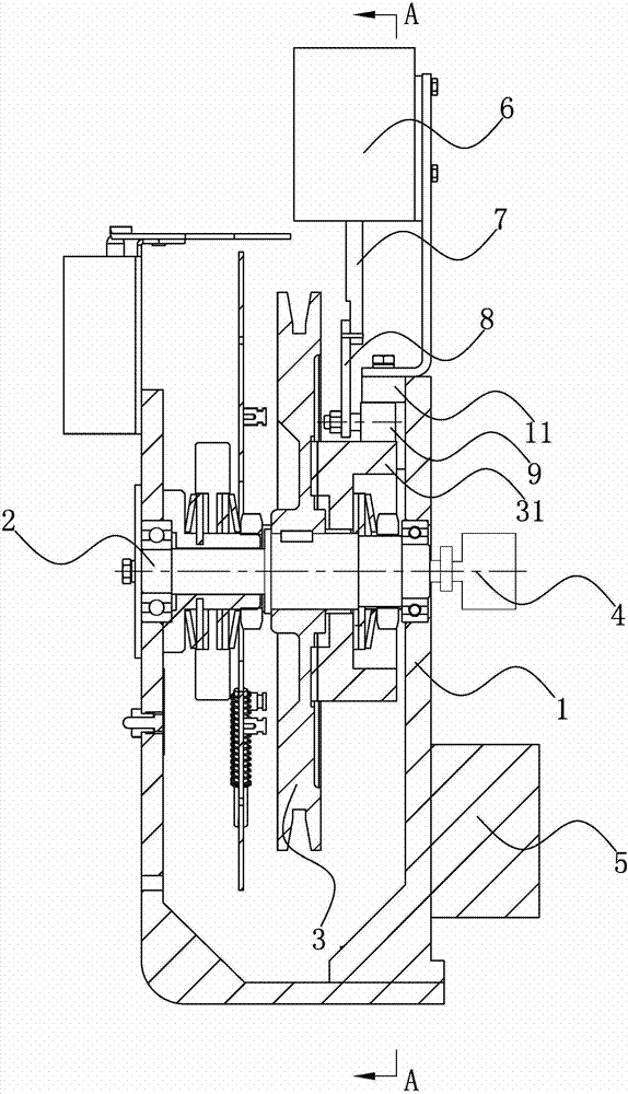
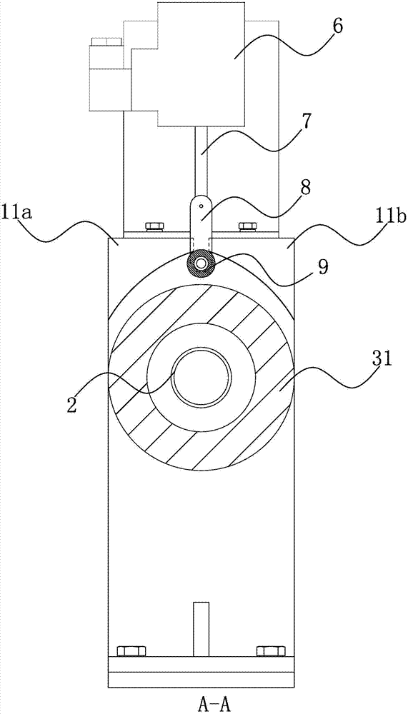
[0025] Such as figure 1 As shown, the sheave brake of the present invention includes a bracket 1, a sheave shaft 2 and a sheave 3, and also includes a sensor 4, a PLC controller 5, an electromagnet 6, a push rod 7, a connecting rod 8, a roller 9, a stop disc 31 and Boss 11.

[0026] The support 1 is fixed with a sheave shaft 2 through a bearing. The sheave shaft 2 is keyed to the sheave 3, and the sheave shaft 2 is fixedly connected to the sensor 4 through a coupling. The sensor 4 is connected with the PLC controller 5 through brushes and wires. The PLC controller 5 is connected with the electromagnet 6 through wires. Described electromagnet 6 is fixedly connected with support 1, and electromagnet 6 is positioned at the top of support 1, and electromagnet 6 is provided with two electromagnets with the same direction of magnetic field line inside, and is provided with between two electromagnets with the same direction of magnetic field line. Spring, electromagnet 6 bottom i...

Embodiment 2

[0036] Such as image 3 As shown, the difference between Embodiment 2 and Embodiment 1 is that a groove is provided at the highest point of the lower end surface of the boss 11 . The width of the groove is smaller than the diameter of the roller 9 . The electromagnet 6 is internally provided with two electromagnets whose magnetic field lines are in opposite directions, and a spring is arranged between the two electromagnets whose magnetic field lines are in opposite directions. When the electromagnet 6 is energized, the two electromagnets whose magnetic induction lines are opposite to each other repel each other, and the output part of the electromagnet 6 can push the push rod 7 downward, and keep it at the lowest position. When the electromagnet 6 is powered off , the spring inside the electromagnet 6 can pull the output part back, so that the electromagnet 6 can pull the push rod 7 upwards and keep it at the highest position.

[0037] The working process of embodiment 2 is...


PUM


Abstract

The invention discloses a brake device or a pawl device used for acting between the inner surface of a shaft, a cage or a skip and the inner surface of a fixing and guiding component or a winch gallery or a lift shaft, and aims at providing a rope wheel brake which is simple in structure, high in safety and capable of closing a rope wheel according to other signals. According to the rope wheel brake, a PLC receives a signal of a sensor, makes a judgment and controls an electromagnet to enable the electromagnet to control a push rod and a connecting rod, and the effect of controlling idler wheels to move up and down is achieved. The distance between the lower end face of a boss and the circumferential face of a brake disc becomes smaller gradually, the brake disc radial direction component force of the pressure between the idler wheels on one side and the lower end face of the boss and the upper end face of the brake disc on the other side becomes larger gradually, the brake disc radial direction component force of the rotation force of the brake disc becomes larger gradually, the friction force becomes larger gradually, and the brake disc is braked. The effect of rope wheel braking is achieved through the contacted friction force between the brake disc and the rope wheel.

Description

technical field [0001] The present invention relates to a control device for an elevator, in particular to a brake or pawl device for acting between a car, cage or skip and a fixed guide element or hoistway or the inner surface of the elevator shaft. Background technique [0002] "It was so miserable, the blood vessels in his neck were torn, and blood was sprayed everywhere in the elevator room!" The witness, Mr. Chen, was still shaking when he recalled it. At about 11:30 on May 15, 2013, in the No. 1 elevator of Changhong Building, Sungang East Road, a female intern nurse of Pengcheng Hospital was caught in the head while taking the elevator, and the elevator finally fell to the first floor. The woman died at the scene. The management office said that the initial suspicion was that the accident occurred due to a malfunction of the elevator. [0003] my country's utility model patent elevator speed limiter, the authorized announcement number is CN201211988Y, and the author...

Claims


Application Information

Patent Timeline
IPC IPC(8): B66B5/02B66B7/00
Inventor 海立冬贾砚华周军然王晓会刘全和
Owner HEBEI DONGFANG FUDA MACHINERY
Why Eureka
Try Eureka