Transient electromagnetic well logging excitation method

A transient electromagnetic logging and electromagnetic logging technology, applied in surveying, earth-moving drilling, wellbore/well components, etc., can solve the problems of low transmitting probe energy, low signal-to-noise ratio, low useful signal amplitude, etc.

Inactive Publication Date: 2014-02-19
CHINA PETROCHEMICAL CORP +1
View PDF7 Cites 11 Cited by
  • Summary
  • Abstract
  • Description
  • Claims
  • Application Information

AI Technical Summary

Problems solved by technology

This measurement method is greatly affected by the contact between the electrode and the casing, and is greatly affected by factors such as casing corrosi...

Method used


Image

  • Transient electromagnetic well logging excitation method
  • Transient electromagnetic well logging excitation method

Examples


Embodiment 1

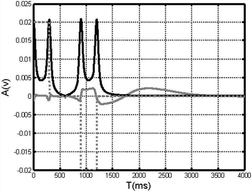
[0018] Implementation example 1: Under the condition of cased hole, the transient electromagnetic logging instrument made of coil (the electromagnetic logging instrument based on the transmitting coil and the receiving coil, the electromagnetic logging instrument with the transmitting and receiving coil is placed in the well, and the transmitting , The axis of the receiving coil coincides with the central axis of the well, so that the emitted electromagnetic field is axisymmetric; the excitation mode of the transient current source is used to periodically excite the coil) according to figure 1 The excitation waveform shown by the dotted line is excited. After the positive current excitation is extended for 300ms, it is disconnected and delayed for 600ms. After that, the negative current, that is, the reverse current is excited for 300ms and then disconnected again to form an excitation cycle. After disconnecting again, the delay is 5000ms. , the response to the above-mentioned ...

Embodiment 2

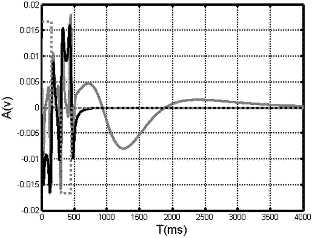
[0019] Implementation example 2: Under the condition of cased hole, the transient electromagnetic logging instrument made of coil is according to figure 2 The excitation waveform shown by the dotted line is excited. After the positive current excitation is extended for 150ms, it is disconnected and delayed for 150ms. After that, the negative current, that is, the reverse current is excited for 150ms and then disconnected again to form an excitation cycle. After disconnecting again, the delay is 5000ms. , the response to the above-mentioned transient electromagnetic excitation is measured during this time, and the waveforms related to formation resistivity have extreme values ​​around 700ms and 1300ms, respectively, while the cased hole response (dark solid line) responds during this time The value is monotonically decreasing.

[0020] The cased-hole response is mainly shown by the dark solid line, and the light-colored solid line is obtained by removing the cased-hole respons...


PUM


Abstract

The invention discloses a transient electromagnetic well logging excitation method. The transient electromagnetic well logging excitation method is based on electromagnetic well logging instruments with transmitting coils and receiving coils. The transient electromagnetic well logging excitation method includes placing the electromagnetic well logging instruments with the transmitting coils and the receiving coils in wells and coinciding the axes of the transmitting coils and the axes of the receiving coils with the central axes of the wells so that transmitted electromagnetic fields are axially symmetrical; periodically exciting the coils by transient power sources. The transient electromagnetic well logging excitation method has the advantages that positive and negative excitation waveforms are adjusted, so that the electromagnetic fields with different frequency combinations and corresponding secondary fields can be excited from the barefoot wells or cased wells, the waveforms which are formed by the secondary fields relevant to formation specific resistance have extreme values and are positioned away from response of holes or casings of the high-amplitude barefoot wells, in other words, formation specific resistance response signals in time domains are independent and can be individually processed, and the formation specific resistance can be acquired; the transient electromagnetic well logging excitation method in the scheme can be implemented in the barefoot wells and the cased wells, and the shapes of the excitation waveforms in the barefoot wells are different from those of the excitation waveforms in the cased wells.

Description

technical field [0001] The present invention relates to a matching method for special instruments for measuring formation electrical parameters, an excitation method for transient electromagnetic logging instruments in the technical field, in particular a non-contact measuring method for effectively measuring formation resistivity in open-hole and cased-hole wells And the excitation mode of the corresponding instrument. Background technique: [0002] In the process of petroleum exploration and development, formation resistivity measured from open hole and cased well is an important parameter to evaluate formation oil saturation. In particular, the formation resistivity measured in the cased hole is an important means to optimize the development plan, and is also one of the important contents of engineering applications such as enhanced oil recovery. In the prior art, there are dual-induction, array-induction and dual-lateral methods for resistivity logging in open-hole w...

Claims


Application Information

Patent Timeline
IPC IPC(8): E21B47/00E21B49/00
Inventor 董经利沈建国臧德福张守伟沈洪楚
Owner CHINA PETROCHEMICAL CORP
Why Eureka
Try Eureka