Centrifugal fan lamp device and air blowing method thereof

A technology of centrifugal fans and lamps, which is applied to pump devices, lighting devices, lighting devices, etc., which can solve problems such as large kinetic energy, inconspicuous air flow, airway disturbance, etc., and achieve the effect of short path, cool and quiet environment

Inactive Publication Date: 2014-02-19
HALSEY ENTERPRISE
View PDF6 Cites 3 Cited by
  • Summary
  • Abstract
  • Description
  • Claims
  • Application Information

AI Technical Summary

Problems solved by technology

[0002] In the prior art, the practice of the ceiling fan is nothing more than the structure of the axial flow fan 9, such as Figure 12 As shown in an existing ceiling fan 9, the source of the air volume generated depends on the return air efficiency from the fan blade to the ceiling. If the return air space is insufficient, the pressure difference on both sides of the fan blade 91 will be greatly reduced, resulting in inconspicuous air flow.
Most indoor spaces have objectively limited heights, so the safe height (210cm from the bottom of the fan blade to the floor) and the best working space (> 50cm from the fan blade to the ceiling) have become limitations in use, and exposed The fan blades are easy to cause a sense of oppression and threat in use and glare caused by light reflection
[0003] Chinese patent announcement number is that the patent of CN2357164 discloses a kind of multifunctional ventilating fan, and this multifunctional ventilating fan adopts traditional forward-leaning type centrifugal fan blade, as Figure 13 As shown, although theoretically the maximum kinetic energy and theoretical head of the three types of centrifugal fan blades can be obtained, they are subject to such Figure 14 The design of the air-gathering outlet 93 of the volute 92 shown causes the air passage formed on the wall to generate turbulence, and the forward-leaning fan blade has a large kinetic energy and a large air volume, according to the kinetic energy loss of the fluid in the flow passage and the square of the velocity Therefore, the loss of the existing forward-leaning centrifugal fan blade matched with the volute 32 is the largest among the three

Method used


Image

  • Centrifugal fan lamp device and air blowing method thereof
  • Centrifugal fan lamp device and air blowing method thereof
  • Centrifugal fan lamp device and air blowing method thereof

Examples


Embodiment Construction

[0073] In order to further illustrate the purpose of the present invention, the technical means used and the technical effect thereof, preferred embodiments will be described in detail as follows:

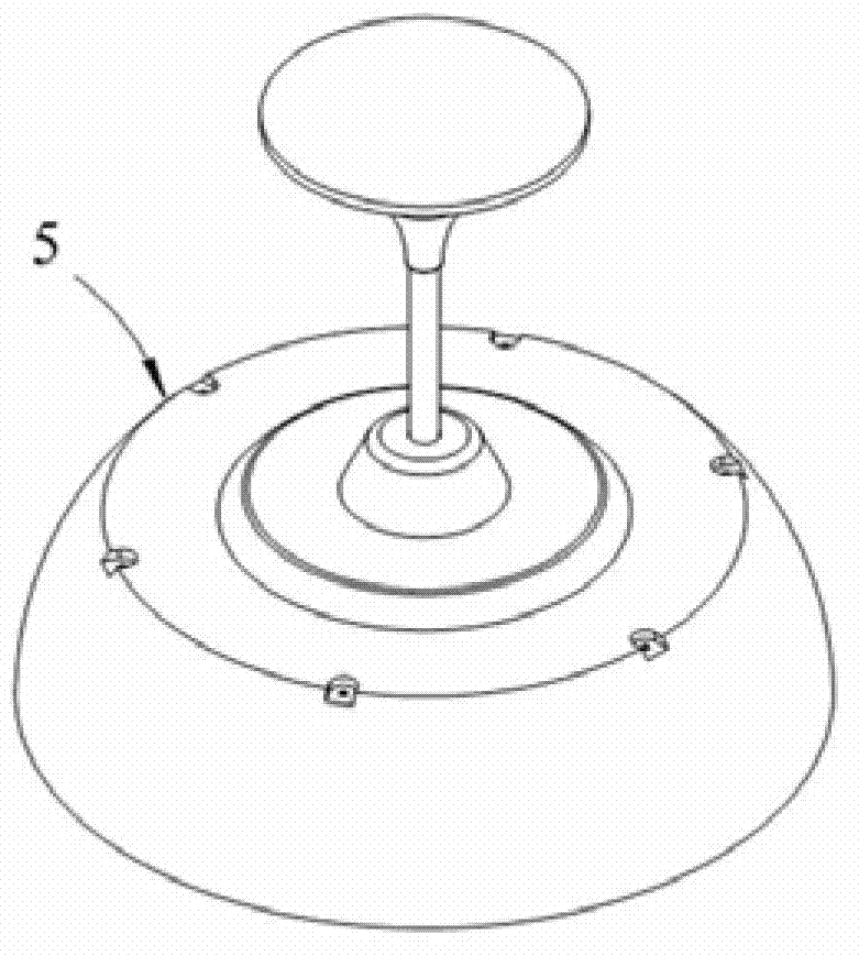
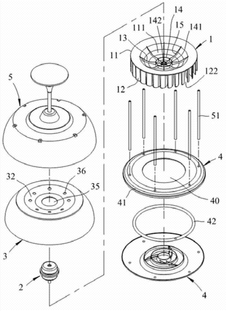
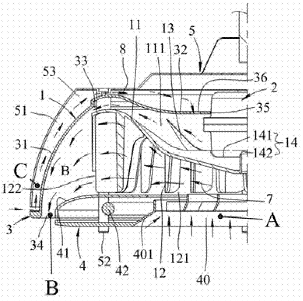
[0074] refer to Figure 1 to Figure 3 , the present invention provides a centrifugal fan lighting device, comprising: a centrifugal fan 1, a motor 2, a volute 3, an annular lampshade 4 and a housing 5; wherein,

[0075] Centrifugal fan 1, a top end piece 11 of the centrifugal fan 1 is an upper concave portion 111, a forward-leaning centrifugal fan blade 12 is provided below the top end piece 11, an auxiliary fan blade 13 is provided on the surface of the upper concave portion 111, and The plurality of forward-leaning centrifugal fan blades 12 jointly form a central air outlet 121 and a surrounding air outlet 122; the junction of the top piece 11 of the centrifugal fan 1 and the motor 2 is provided with a junction 14, and the junction 14 is provided There is an inner groove 141 , a...


PUM


Abstract

The invention provides a centrifugal fan lamp device and an air blowing method thereof. The centrifugal fan lamp device is formed by hiding a centrifugal fan in a lamp device. Two fan blades opposite in directions are arranged on the centrifugal fan driven by a motor, a first flow passage and a second flow passage which are matched with the centrifugal fan are arranged in the lamp device, and the second flow passage converges into the first flow passage. The shape of one of the fan blades of the centrifugal fan inclines forwards, therefore, the lamp device can sucks air form the center of the position right below the lamp device, plenty of air is blown out from the periphery of the center of the position right below the lamp device, the lamp device is provided with a narrow air outlet, then large lift is obtained, and a certain amount of air flow can be maintained.

Description

technical field [0001] The invention relates to a centrifugal fan lighting device and its blowing method, in particular to a multi-blade centrifugal fan hidden in the lighting device, using the centrifugal force generated when the centrifugal fan operates at high speed, so that the airflow can be smoothly accelerated and sent out A centrifugal fan lighting device with a large air volume and a relatively long lift and a blowing method thereof. Background technique [0002] In the prior art, the practice of the ceiling fan is nothing more than the structure of the axial flow fan 9, such as Figure 12 As shown in an existing ceiling fan 9, the source of the air volume depends on the return air efficiency from the fan blade to the ceiling. If the return air space is insufficient, the pressure difference on both sides of the fan blade 91 will be greatly reduced, resulting in inconspicuous air flow. Most indoor spaces have objectively limited heights, so the safe height (210cm fro...

Claims


Application Information

Patent Timeline
Patent Type & Authority Applications(China)
IPC IPC(8): F04D25/08F21V33/00
Inventor 曾耕文李政昌
Owner HALSEY ENTERPRISE
Why Eureka
Try Eureka