Supercharge Your Innovation With Domain-Expert AI Agents!

Spiral elastic piece heat dissipation driven disk assembly

An elastic sheet and spiral technology, applied in the field of clutches, can solve the problems of accelerating clutch wear, reducing clutch service life, adverse effects of clutch heat dissipation, etc., to achieve the effect of reducing wear and prolonging service life

Inactive Publication Date: 2014-02-19
WUHU HONGYAO AUTOMOBILE IND
View PDF9 Cites 0 Cited by
  • Summary
  • Abstract
  • Description
  • Claims
  • Application Information

AI Technical Summary

Problems solved by technology

However, during the power transmission process of the diaphragm spring clutch, parts will collide at the moment of separation and engagement, which will accelerate the wear of the clutch and reduce the service life of the clutch; Adding elastic plates will adversely affect the heat dissipation of the clutch

Method used


Image

  • Spiral elastic piece heat dissipation driven disk assembly
  • Spiral elastic piece heat dissipation driven disk assembly

Examples


Embodiment Construction

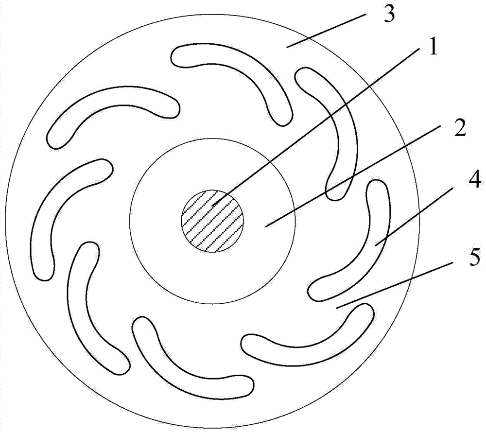
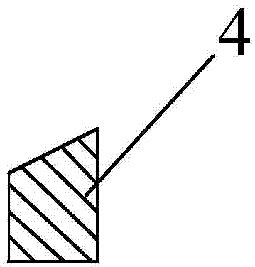
[0013] Such as figure 1 and figure 2 as shown, figure 1 It is a front view of a helical elastic heat dissipation driven plate assembly in the embodiment of the present invention; figure 2 yes figure 1 Schematic diagram of the cross-sectional structure of the middle elastic sheet.

[0014] refer to figure 1 , the embodiment of the present invention provides a helical elastic plate cooling driven disk assembly, including: driven disk 3, damping disk 2 and disk hub 1; driven disk 3 is fixedly connected with vibration damping disk 2 through rivets Set on the hub 1, an elastic pad is provided at the connecting part of the driven disk 3 and the damping disk 2; a plurality of spirally distributed elastic sheets 4 are arranged on the circumference of the driven disk 3, and the space between two adjacent elastic sheets 4 Airflow channels 5 are formed.

[0015] In a specific embodiment, the elastic piece 4 has a long arc structure, the outer arc of the elastic piece 4 faces the ...


PUM


Abstract

The invention discloses a spiral elastic piece heat dissipation driven disk assembly. The spiral elastic piece heat dissipation driven disk assembly comprises a driven disk, a vibration damping disk and a disk hub, wherein the driven disk is fixed to the vibration damping disk in a riveted mode and arranged on the disk hub in a sleeved mode, a plurality of elastic pieces distributed spirally are evenly arranged on the circumference of the driven disk, and an airflow channel for heat dissipation is formed between every two adjacent elastic pieces. According to the spiral elastic piece heat dissipation driven disk assembly, the multiple elastic pieces distributed spirally are distributed on the driven disk, collision between components is buffered through the buffering effect of the elastic pieces, when the driven disk rotates, airflow passing through the gaps between the spirally distributed elastic pieces can accelerate heat dissipation, abrasion to a clutch is recued, and service life is prolonged.

Description

technical field [0001] The invention relates to the technical field of clutches, in particular to a helical elastic plate cooling driven plate assembly. Background technique [0002] The automobile clutch is located in the flywheel housing between the engine and the gearbox, and the clutch assembly is fixed on the rear plane of the flywheel with screws, and the output shaft of the clutch is the input shaft of the gearbox. During the driving process of the car, the driver can step on or release the clutch pedal as needed to temporarily separate and gradually engage the engine and the transmission, so as to cut off or transmit the power input from the engine to the transmission. [0003] The diaphragm spring clutch is a clutch made by replacing the general coil spring and release lever mechanism with a diaphragm spring. Because it is arranged in the center, it can also be regarded as a central spring clutch. Diaphragm spring is a conical spring piece made of thin spring steel...

Claims


Application Information

Patent Timeline
Patent Type & Authority Applications(China)
IPC IPC(8): F16D13/64F16D13/72
Inventor 潘燕斌
Owner WUHU HONGYAO AUTOMOBILE IND
Features
  • R&D
  • Intellectual Property
  • Life Sciences
  • Materials
  • Tech Scout
  • Unparalleled Data Quality
  • Higher Quality Content
  • 60% Fewer Hallucinations
Learn More