The Method of Realizing the Zero Point Calibration of Polar Coordinate Gear Measuring Center by Using Standard Block
A technology of gear measurement and zero point calibration, which is applied in the direction of measuring devices, mechanical measuring devices, and mechanical devices, etc., can solve the problems of automatic error compensation, no polar coordinate calibration, no T automatic detection device and method, etc., and reach the scope of application Wide, simple method, simple structure effect
- Summary
- Abstract
- Description
- Claims
- Application Information
AI Technical Summary
Problems solved by technology
Method used
Image
Examples
Embodiment 1
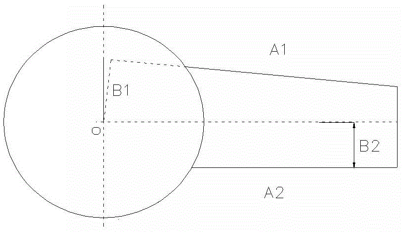
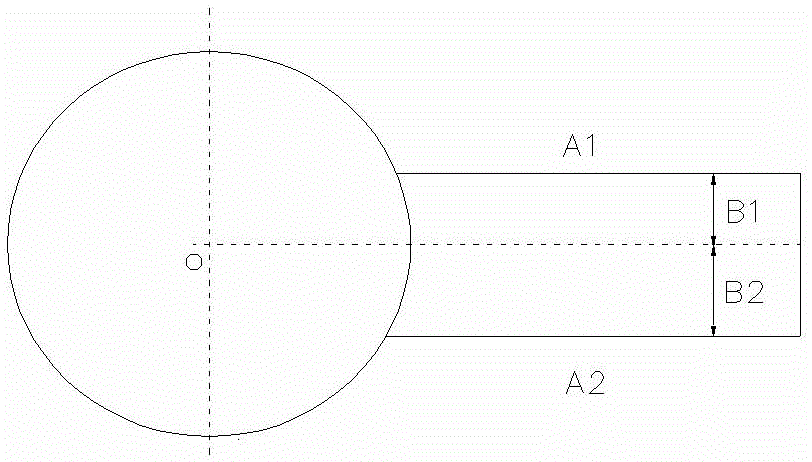
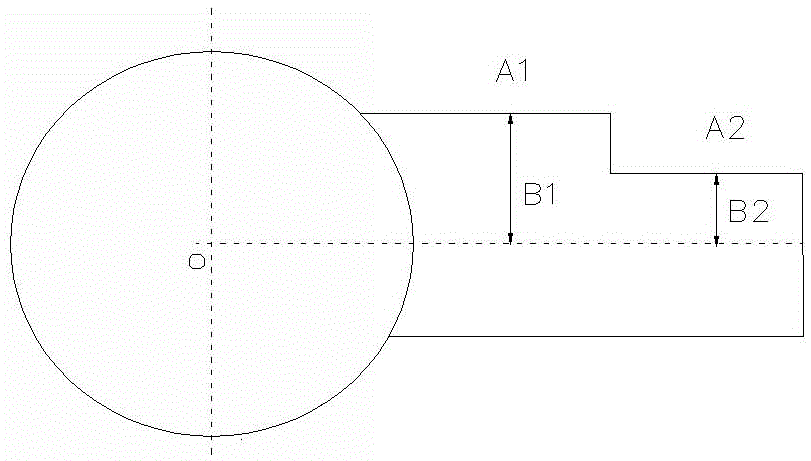
[0035] see Figure 5 , the measuring instrument is the polar coordinate gear measuring center. Using a one-dimensional needle-point probe, the measuring force is perpendicular to the R direction, and the offset of the probe is T 0 A known. Utilize the concrete steps of the inventive method to be:
[0036] The first step: Clamp the standard block on the rotary axis table of the polar coordinate gear measurement center, and place the measuring head in a suitable position in the R and Z directions, so as to ensure that the standard block can make a datum under the drive of the turntable Surface contact with the upper probe;
[0037] Step 2: Driven by the rotating shaft of the polar coordinate gear measurement center, the standard block is brought into contact with the probe, so that the reference plane A of the standard block is 1 Touch the upper probe; obtain the coordinate values of each axis of the contact point on the standard block (R 1 ,q 1 );
[0038] Step 3: Auto...
Embodiment 2
[0045] see Figure 4 with Figure 5 , the measuring instrument is the polar coordinate gear measuring center. A one-dimensional spherical probe is used, the measuring force is perpendicular to the R direction, and the offset of the probe is T 0 unknown. Utilize the concrete steps of the inventive method to be:
[0046] The first step: Clamp the standard block on the rotary axis table of the polar coordinate gear measurement center, and place the measuring head in a suitable position in the R and Z directions, so as to ensure that the standard block can make a datum under the drive of the turntable Side A 1 touch the probe;
[0047]Step 2: Driven by the rotating shaft of the polar coordinate gear measurement center, the standard block is brought into contact with the probe, so that the reference plane A of the standard block is 1 Touch the upper probe; obtain the coordinate values of each axis of the contact point on the standard block (R 1 ,q 1 );
[0048] Step 3: A...
Embodiment 3
[0057] see Figure 5 , the measuring instrument is a well-known gear measuring center. Using a one-dimensional needle tip probe, the force is measured perpendicular to the R direction. Utilize the concrete steps of the inventive method to be:
[0058] Step 1: Clamp the standard block on the rotary shaft table of the gear measurement center, and place the measuring head in a suitable position in the R and Z directions, so that the standard block can make a datum plane A under the drive of the turntable 1 touch the probe;
[0059] Step 2: Driven by the rotating shaft of the gear measurement center, the standard block is brought into contact with the measuring head, so that the reference plane A of the standard block is 1 Touch the upper probe; obtain the coordinate values of each axis of the contact point on the standard block (R 1 ,q 1 ,T 1 );
[0060] Step 3: Automatically change the position of the measuring head along the R direction, and drive the standard block to...
PUM
 Abstract
Description
Claims
Application Information
 - R&D
- Intellectual Property
- Life Sciences
- Materials
- Tech Scout
- Unparalleled Data Quality
- Higher Quality Content
- 60% Fewer Hallucinations
Browse by: Latest US Patents, China's latest patents, Technical Efficacy Thesaurus, Application Domain, Technology Topic, Popular Technical Reports.
© 2025 PatSnap. All rights reserved.Legal|Privacy policy|Modern Slavery Act Transparency Statement|Sitemap|About US| Contact US: help@patsnap.com


