Method and system for testing antenna impedance

A technology of antenna impedance and test system, which is applied in the direction of measuring resistance/reactance/impedance, measuring devices, measuring electrical variables, etc., can solve problems such as low signal-to-noise ratio, non-linear devices do not meet the transmission power frequency, etc., to improve authenticity Effect

Active Publication Date: 2014-02-19
NO 722 RES INST OF CHINA SHIPBUILDING IND
View PDF4 Cites 11 Cited by
  • Summary
  • Abstract
  • Description
  • Claims
  • Application Information

AI Technical Summary

Problems solved by technology

[0011] In short, the disadvantages of the above methods are as follows: first, the signal-to-noise ratio of the measurement is low, the maximum is about one-tenth; second, the frequency requirements of the nonlinear device impedance measurement do not meet the actual transmission frequency

Method used


Image

  • Method and system for testing antenna impedance
  • Method and system for testing antenna impedance
  • Method and system for testing antenna impedance

Examples


Embodiment Construction

[0037] In order to make the object, technical solution and advantages of the present invention clearer, the present invention will be further described in detail below in conjunction with the accompanying drawings and embodiments. It should be understood that the specific embodiments described here are only used to explain the present invention, not to limit the present invention.

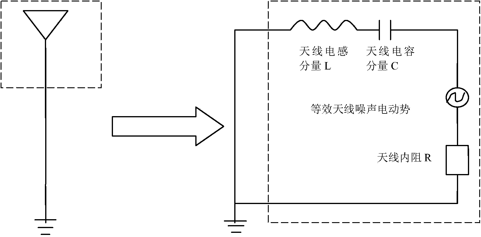
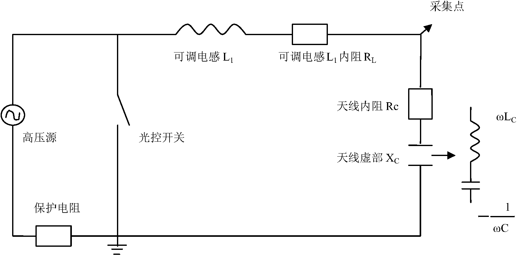
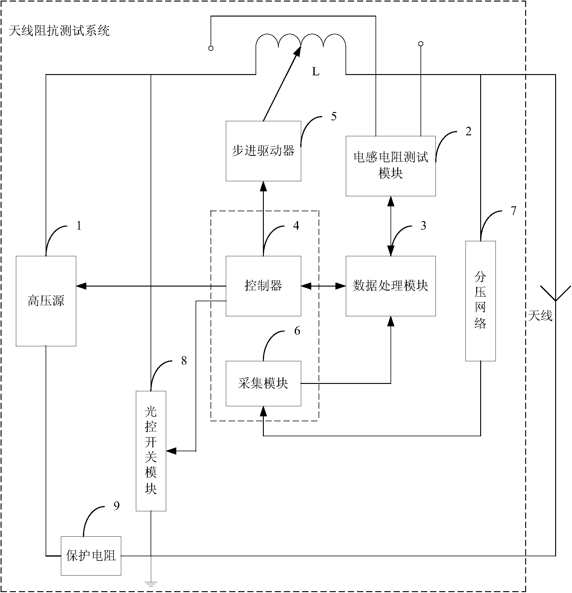
[0038] In the present invention, an LC series self-attenuation resonant circuit composed of an LC series self-attenuation resonant circuit composed of an antenna equivalent capacitance C fed into a DC high voltage and a known adjustable inductance L, and the self-attenuation at the required frequency are generated by adjusting the inductance value of the adjustable inductance oscillation. The discrete values ​​of the self-attenuating oscillation transient response voltage and time are obtained through circuit sampling, and the antenna impedance value is obtained through calculation and curve fittin...


PUM


Abstract

The invention discloses a system for testing antenna impedance. The system for testing the antenna impedance comprises a tested antenna, a high-voltage power source, an adjustable inductor L, an inductance and resistance testing module, a data processing module, a controller, a stepping driver, a gathering module, a potential-divider network, a light-operated switch module and a protection resistor. According to a working mechanism, oscillating starting initial high voltage is injected into a self-damping oscillation circuit with the frequency selectable so that self-damping oscillation can be generated; self-damping oscillation physical characteristics are commonly determined by parameters of elements so that the resistance value of the antenna to be tested can be obtained through sampling and calculation conducted on the oscillation voltage. According to the system for testing the antenna impedance, the testing signal-to-noise ratio can be effectively improved and under the actual emitting operating frequency of the antenna, accurate measurement of the antenna impedance is conducted.

Description

technical field [0001] The national defense invention patent belongs to the technical field of radio communication antenna testing, and specifically relates to a low frequency antenna (very low frequency, ultra low frequency, extremely low frequency) impedance test method and test system. Background technique [0002] The size of the communication antenna is determined by the communication wavelength. Due to the large size of the low-frequency communication (very low frequency, ultra-low frequency, and extremely low frequency) antenna, the electrostatic induction is strong. Its surface electrostatic induction can reach 2000v, which makes it impossible for common antenna testing equipment to perform antenna impedance testing. The low-frequency communication design, construction, commissioning, maintenance, and on-site online transmission all require on-site accurate measurement of antenna impedance. [0003] In the prior art, there are mainly the following three methods for ...

Claims


Application Information

Patent Timeline
Patent Type & Authority Applications(China)
IPC IPC(8): G01R27/02
Inventor 王继红江传华江思杰郭彧琦
Owner NO 722 RES INST OF CHINA SHIPBUILDING IND
Why Eureka
Try Eureka