
Asynchronous permanent magnet synchronous generator

A permanent magnet synchronous and generator technology, applied in asynchronous induction motors, synchronous motors with stationary armatures and rotating magnets, electrical components, etc., can solve problems such as low engine efficiency, penetration, affecting power supply quality, etc. The effect of reliable operation

Inactive Publication Date: 2014-02-19
孙屹东
View PDF11 Cites 7 Cited by
  • Summary
  • Abstract
  • Description
  • Claims
  • Application Information

AI Technical Summary

Problems solved by technology

[0003] The asynchronous generator is simple, reliable, and easy to maintain. It can be directly connected to the grid for power generation, and the speed of the prime mover is variable. However, the asynchronous generator needs to absorb reactive power from the grid, which affects its power factor, and the efficiency of the engine is relatively low. And there is a problem of low voltage penetration
Synchronous generator is the basis of grid power generation. The efficiency of generator is relatively high, but synchronous power generation requires the speed of generator to adapt to the frequency of the grid. The speed of the prime mover must be fixed and cannot be changed with the requirements of the prime mover. For power generation, an electronic inverter system needs to be added. Due to the complexity and technical difficulty of the inverter system, the reliability of the system is affected, and the investment is increased. High-order harmonics are also generated during operation, which affects the quality of power supply.

Method used


Image

  • Asynchronous permanent magnet synchronous generator
  • Asynchronous permanent magnet synchronous generator
  • Asynchronous permanent magnet synchronous generator

Examples


Embodiment Construction

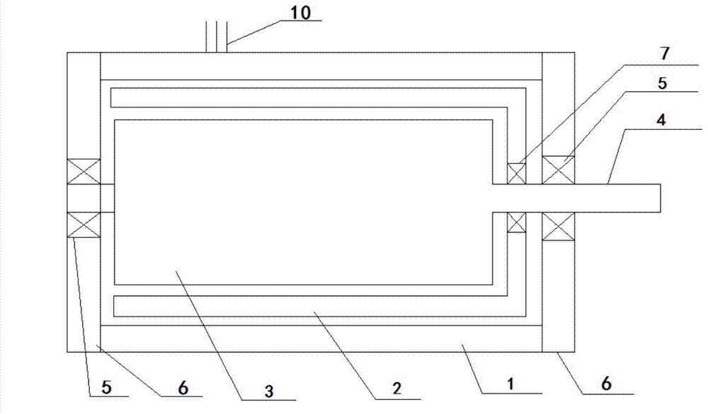
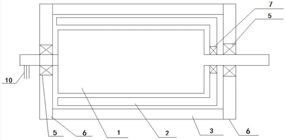
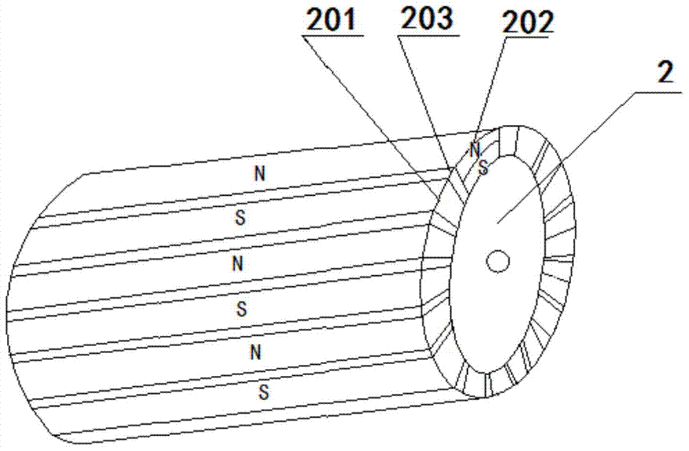
[0024] see figure 1 It can be seen that the asynchronous permanent magnet synchronous generator is mainly composed of a wound stator 1, a driving rotor 3, a driven rotor 2, an end cover 6, bearings 5, 7, a power lead wire 11 and a rotating shaft 4 to form an outer stator generator or an inner stator generator. Engine; the generator of this application is to add a driven rotor 2 between the winding stator 1 and the driving rotor 3 of the existing horizontal generator.

[0025] The wound stator 1 of the inner rotor generator is fixedly connected to the end covers 6 on both sides, the active rotor 3 is connected to the rotating shaft 4, the rotating shaft 4 is connected to the power machine, and the active rotor 3 is supported in the wound stator 1 through the bearing 5 on the rotating shaft 4 The driven rotor 2 is fixed between the driving rotor 3 and the winding stator 1 through bearings 7 on both side end covers 6 .

[0026] Among them, the active rotor 3 of the external roto...


PUM


Abstract

The invention discloses an asynchronous permanent magnet synchronous generator. The asynchronous permanent magnet synchronous generator comprises a winding stator, a driving rotor, a driven rotor, end covers, bearings and a rotating shaft. The winding stator is fixedly connected with the end covers on the two sides, the driving rotor is connected with the rotating shaft and supported by the end covers, in the winding stator, on the two sides through one bearing on the rotating shaft, the driven rotor is fixed between the driving rotor and the winding stator through the other bearing, and the rotating shaft is connected with a power machine. The horizontal type generator can asynchronously run and synchronously generate electricity, the speed of the motive power machine of the generator can change within a certain range, the generator has the characteristics of a synchronous generator, a complex inverter system does not need to be invested, and the asynchronous permanent magnet synchronous generator can simply, safely and reliably run like an asynchronous generator.

Description

technical field [0001] The invention relates to a generator, in particular to a power generation device capable of asynchronous operation and synchronous power generation. Background technique [0002] Traditional generators are divided into asynchronous and synchronous generators, the main components of which include stators and rotors. Whether it is a synchronous generator or an asynchronous generator, each has its own advantages and disadvantages, and is suitable for different prime movers. [0003] The asynchronous generator is simple, reliable, and easy to maintain. It can be directly connected to the grid for power generation, and the speed of the prime mover is variable. However, the asynchronous generator needs to absorb reactive power from the grid, which affects its power factor, and the efficiency of the engine is relatively low. And there is a problem of low voltage penetration. Synchronous generator is the basis of grid power generation. The efficiency of gene...

Claims


Application Information

Patent Timeline
IPC IPC(8): H02K16/02
CPCH02K16/02H02K17/16H02K21/16
Inventor 孙屹东
Owner 孙屹东
Learn More