Magnetic force suspension robot for operation of overhead high-tension power transmission line

A technology of high-voltage transmission lines and robots, applied in the direction of overhead lines/cable equipment, holding devices with magnetic attraction or thrust, electrical components, etc., can solve problems such as harmful dynamic loads, low cruising speed, harmful friction, etc., and achieve the elimination of harmful Abrasion, increased movement speed, and low cost effects

Inactive Publication Date: 2014-02-19
HUBEI UNIV OF TECH
View PDF10 Cites 23 Cited by
  • Summary
  • Abstract
  • Description
  • Claims
  • Application Information

AI Technical Summary

Problems solved by technology

[0007] The invention mainly solves the problem of slipping and harmful friction caused by the existing wheel-rail moving mode of the overhead high-voltage transmission line operation robot; it provides a zero-contact, zero-friction and magnetic suspension robot for overhead high-voltage transmission line operation that can eliminate the slipping problem
[0008] Another purpose of the present invention is to solve the problem of low cruising speed of the overhead high-voltage transmission line operation robot in the barrier-free line section between poles and towers; to provide a high-efficiency overhead high-voltage transmission line operation magnetic levitation robot
[0009] Another object of the present invention is to solve the harmful dynamic load problem caused by the vibration of the existing wheel-rail moving mode of the overhead high-voltage transmission line operation robot; to provide an overhead high-voltage transmission line that can avoid the harmful dynamic load caused by the vibration Working Magnetic Levitation Robot

Method used


Image

  • Magnetic force suspension robot for operation of overhead high-tension power transmission line
  • Magnetic force suspension robot for operation of overhead high-tension power transmission line
  • Magnetic force suspension robot for operation of overhead high-tension power transmission line

Examples


Embodiment Construction

[0039] Below by embodiment, in conjunction with accompanying drawing, technical scheme of the present invention is described further in detail:

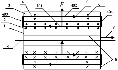
[0040] see figure 1 — Figure 9 , the magnetic levitation method of the robot working on the overhead high-voltage transmission line, the robot can be suspended by using the magnetic field generated by the high-voltage current on the ampere force of the current-carrying wire; The suspension tile 8 is composed of an inner lining tile 1, a magnetic core 2, an outer lining tile 3 and a rectangular coil 4.

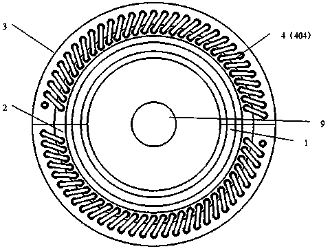
[0041] see Figure 6 and Figure 10 , the inner lining tile 1 is made of weakly magnetically permeable material and is in the shape of a semicircular tube, which is used to protect and support the magnetic core 2. The outer cylindrical surface of the inner lining tile 1 is connected with the inner cylindrical surface of the magnetic core 2; the inner cylindrical surface of the inner lining tile 1 The surface radius is 30mm, the o...


PUM


Abstract

A magnetic force suspension robot for the operation of an overhead high-tension power transmission line comprises two suspension bushes (8), wherein the suspension bushes (8) can be opened or closed and are in central symmetry with a high-tension lead wire (9), each suspension bush (8) comprises a rectangular coil (4), an inner lining bush (1), a magnetic core (2) and an outer lining bush (3), and each inner lining bush (1), the corresponding magnetic core (2) and the corresponding outer lining bush (3) are arranged from inside to outside in sequence. The magnetic force suspension robot for the operation of the overhead high-tension power transmission line has the advantages that the robot can be suspended above the high-tension lead wire, zero contact and zero friction between the robot and the high-tension lead wire are achieved, and thus harmful abrasion and harmful moving loads are eliminated. Under the condition that driving force is available, the moving speed of the robot can be improved greatly through the zero contact and zero friction modes. Through the magnetic force suspension mode, the complexity of the moving mechanism of the robot can be lowered, and the light-weight trend of the robot can be achieved. A magnetic force suspension device is small in size, low in cost and easy to achieve.

Description

technical field [0001] The invention relates to the technical fields of robot technology and magnetic field, in particular to a magnetic levitation robot for overhead high-voltage transmission line operation. Background technique [0002] Overhead high-voltage transmission line operation robots mainly include inspection robots, deicing robots, insulator cleaning robots, etc., as well as other intelligent detection and maintenance equipment. Since the 1980s, robots for overhead high-voltage transmission lines have been a research hotspot in the field of robotics. The United States, Japan, Canada, China and other countries have successively carried out research work on overhead high-voltage transmission line operation robots. In 2008, Japan's Debenest et al. developed an inspection robot named "Expliner" for high-voltage multi-split conductors. In 2000, Montambault and others from the Quebec Hydropower Research Institute in Canada developed a remote control car called HQ Lin...

Claims


Application Information

Patent Timeline
Patent Type & Authority Applications(China)
IPC IPC(8): H02N15/00H02G1/02
Inventor 徐显金杨光友钟飞汤亮杨小俊季永芹
Owner HUBEI UNIV OF TECH
Why Eureka
Try Eureka