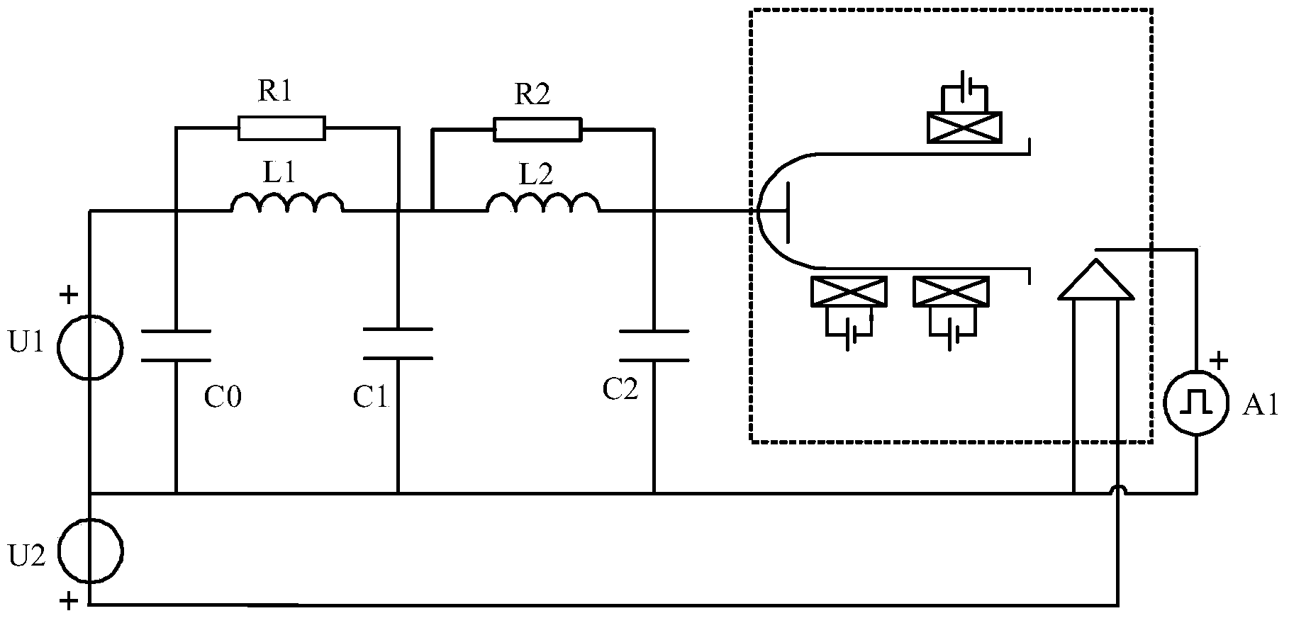
Low-frequency oscillation suppression outer loop of plasma Hall effect thruster
A Hall thruster and Hall effect technology, which is applied in the direction of plasma, plasma utilization, thrust reverser, etc., can solve the problem that the LC outer circuit cannot take into account low-frequency oscillation suppression and power supply protection functions, etc.
- Summary
- Abstract
- Description
- Claims
- Application Information
AI Technical Summary
Problems solved by technology
Method used
Image
Examples
specific Embodiment approach 1
[0012] Specific implementation mode 1. Combination figure 1 Describe this embodiment, the low-frequency oscillation suppression outer circuit of a plasma Hall effect thruster described in this embodiment, which includes a discharge power supply U1, a heating power supply U2, and an igniter A1;
[0013] It also includes No. 1 resistor R1, No. 2 resistor R2, No. 1 inductor L1, No. 2 inductor L2, No. 1 capacitor C0, No. 2 capacitor C1 and No. 3 capacitor C2; One end, one end of the first inductor L1 and one end of the first capacitor C0, the other end of the first resistor R1 is connected to the other end of the first inductor L1, one end of the second resistor R2, one end of the second inductor L2 and the second capacitor One end of C1, the other end of the second resistor R2 are connected to the other end of the second inductor L2, one end of the third capacitor C2 and the anode of the Hall thruster;
[0014] The negative pole of the discharge power supply U1 is simultaneously...
specific Embodiment approach 2
[0017] Specific embodiment 2. This embodiment is a further description of the low-frequency oscillation suppression outer circuit of a plasma Hall effect thruster described in specific embodiment 1. The resistance value of the first resistor R1 is 100Ω, and the resistance value of the second resistor R2 is The resistance is 400Ω, the inductance of the first inductor L1 and the second inductor L2 is 0.1mH, and the capacitance of the first capacitor C0 and the second capacitor C1 is 10uF.
[0018] The resistors described in this embodiment, the rated power of No. 1 resistor R1 and No. 2 resistor R2 is 50W, the maximum current that can pass through the inductor, No. 1 inductor L1 and No. 2 inductor L2 is more than twice the discharge current of the thruster, and the capacitor The No. 1 capacitor C0, the No. 2 capacitor C1 and the No. 3 capacitor C2 have a withstand voltage that is more than twice the discharge voltage of the thruster.
[0019] The No. 1 resistor R1, the No. 1 ind...
specific Embodiment approach 3
[0020] Specific embodiment three. This embodiment is a further description of the low-frequency oscillation suppression outer circuit of a plasma Hall effect thruster described in specific embodiment one. The resistance value of the first resistor R1 is 100Ω, and the resistance value of the second resistor is R2. The resistance value of the first inductor L1 is 0.05mH, the inductive reactance of the second inductor L2 is 0.1mH, the capacitance values of the first capacitor C0 and the second capacitor C1 are both 20uF, and the capacitance of the third capacitor C2 The value is 0.47uF.
PUM
 Abstract
Description
Claims
Application Information
 - R&D
- Intellectual Property
- Life Sciences
- Materials
- Tech Scout
- Unparalleled Data Quality
- Higher Quality Content
- 60% Fewer Hallucinations
Browse by: Latest US Patents, China's latest patents, Technical Efficacy Thesaurus, Application Domain, Technology Topic, Popular Technical Reports.
© 2025 PatSnap. All rights reserved.Legal|Privacy policy|Modern Slavery Act Transparency Statement|Sitemap|About US| Contact US: help@patsnap.com

