
A Plasma Hall Effect Thruster Low-Frequency Oscillation Suppression Outer Circuit

A Hall effect, low-frequency oscillation technology, applied in the direction of plasma, plasma utilization, thrust reverser, etc., can solve the problem that the LC external circuit cannot take into account low-frequency oscillation suppression and power supply protection functions, etc.

Active Publication Date: 2016-09-14
HARBIN INST OF TECH
View PDF5 Cites 1 Cited by
  • Summary
  • Abstract
  • Description
  • Claims
  • Application Information

AI Technical Summary

Problems solved by technology

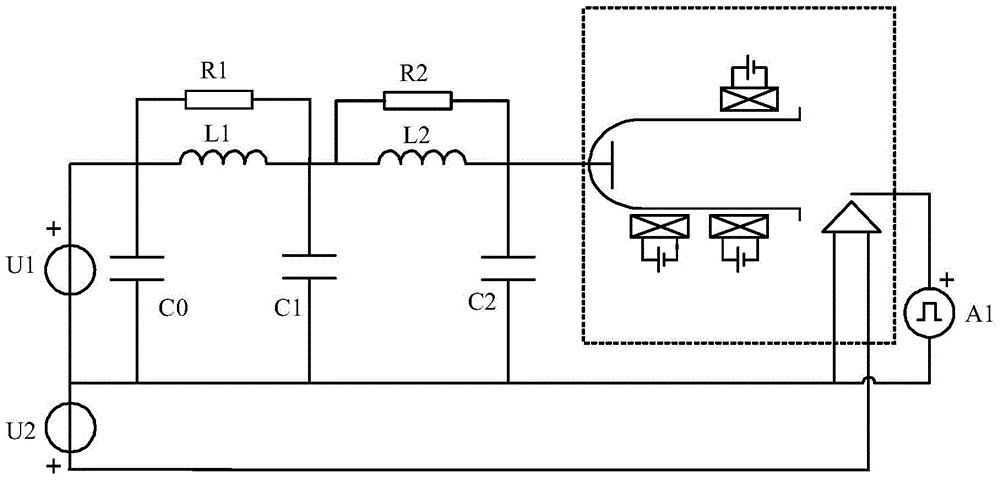
[0004] In order to solve the problem that the existing LC external circuit cannot take into account the functions of low-frequency oscillation suppression and power supply protection, the present invention proposes a low-frequency oscillation suppression external circuit of a plasma Hall effect thruster

Method used


Image

  • A Plasma Hall Effect Thruster Low-Frequency Oscillation Suppression Outer Circuit

Examples


specific Embodiment approach 1

[0012] Specific implementation mode 1. Combination figure 1 Describe this embodiment, the low-frequency oscillation suppression outer circuit of a plasma Hall effect thruster described in this embodiment, which includes a discharge power supply U1, a heating power supply U2, and an igniter A1;

[0013] It also includes No. 1 resistor R1, No. 2 resistor R2, No. 1 inductor L1, No. 2 inductor L2, No. 1 capacitor C0, No. 2 capacitor C1 and No. 3 capacitor C2; One end, one end of the first inductor L1 and one end of the first capacitor C0, the other end of the first resistor R1 is connected to the other end of the first inductor L1, one end of the second resistor R2, one end of the second inductor L2 and the second capacitor One end of C1, the other end of the second resistor R2 are connected to the other end of the second inductor L2, one end of the third capacitor C2 and the anode of the Hall thruster;

[0014] The negative pole of the discharge power supply U1 is simultaneously...

specific Embodiment approach 2

[0017] Specific embodiment 2. This embodiment is a further description of the low-frequency oscillation suppression outer circuit of a plasma Hall effect thruster described in specific embodiment 1. The resistance value of the first resistor R1 is 100Ω, and the resistance value of the second resistor R2 is The resistance is 400Ω, the inductance of the first inductor L1 and the second inductor L2 is 0.1mH, and the capacitance of the first capacitor C0 and the second capacitor C1 is 10uF.

[0018] The resistors described in this embodiment, the rated power of No. 1 resistor R1 and No. 2 resistor R2 is 50W, the maximum current that can pass through the inductor, No. 1 inductor L1 and No. 2 inductor L2 is more than twice the discharge current of the thruster, and the capacitor The No. 1 capacitor C0, the No. 2 capacitor C1 and the No. 3 capacitor C2 have a withstand voltage that is more than twice the discharge voltage of the thruster.

[0019] The No. 1 resistor R1, the No. 1 ind...

specific Embodiment approach 3

[0020] Specific embodiment three. This embodiment is a further description of the low-frequency oscillation suppression outer circuit of a plasma Hall effect thruster described in specific embodiment one. The resistance value of the first resistor R1 is 100Ω, and the resistance value of the second resistor is R2. The resistance value of the first inductor L1 is 0.05mH, the inductive reactance of the second inductor L2 is 0.1mH, the capacitance values ​​of the first capacitor C0 and the second capacitor C1 are both 20uF, and the capacitance of the third capacitor C2 The value is 0.47uF.


PUM


Abstract

A plasma Hall effect thruster low-frequency oscillation suppression outer circuit, the invention relates to the technical field of Hall effect thrusters. The present invention solves the problem that the existing LC external circuit cannot take into account the functions of low-frequency oscillation suppression and power supply protection. The positive electrode of the discharge power supply of the present invention is simultaneously connected to one end of the No. The other end of the resistor is connected to the other end of the No. 1 inductor, one end of the No. 2 resistor, one end of the No. 2 inductor and one end of the No. 2 capacitor, and the other end of the No. 2 resistor is connected to the other end of the No. One end and the anode of the Hall thruster; the negative pole of the discharge power supply simultaneously heats the negative pole of the power supply, the other end of the No. 1 capacitor, the other end of the No. 2 capacitor, the other end of the No. 3 capacitor, the common negative end of the Hall thruster cathode and The negative pole of the igniter, and the positive pole of the igniter are connected to the contact pole of the cathode of the Hall thruster. The invention is applicable to the technical field of Hall effect thrusters.

Description

technical field [0001] The invention relates to the technical field of Hall effect thrusters. Background technique [0002] The plasma Hall effect thruster is a functional conversion device that converts electrical energy into kinetic energy of the working medium by using the joint action of electric field and magnetic field. It is one of the most widely used electric thrusters in space propulsion. Although the operating power supply of the Hall thruster is a DC discharge, the oscillation of the discharge current with a frequency range of about 1 to 100kHz has been observed in the experiment, which is called low-frequency oscillation relative to the plasma oscillation. The peak-to-peak value of the low-frequency oscillation can often reach 100% of the average value of the discharge current. Large-scale low-frequency oscillations will impact the power supply system of the Hall thruster, and may also be connected to other equipment on the satellite, affecting their normal ope...

Claims


Application Information

Patent Timeline
Patent Type & Authority Patents(China)
IPC IPC(8): H05H1/24H02M1/14F03H1/00
CPCF03H1/0018F03H1/0075
Inventor 于达仁魏立秋韩亮丁永杰
Owner HARBIN INST OF TECH
Learn More