Thermal head and thermal printer provided with same
A technology of thermal head and heating part, applied in printing and other directions, can solve problems such as substrate gaps or cracks, and achieve the effect of reducing the possibility of gaps or cracks
- Summary
- Abstract
- Description
- Claims
- Application Information
AI Technical Summary
Problems solved by technology
Method used
Image
Examples
no. 1 approach
[0028] Hereinafter, a first embodiment of the thermal head of the present invention will be described with reference to the drawings.
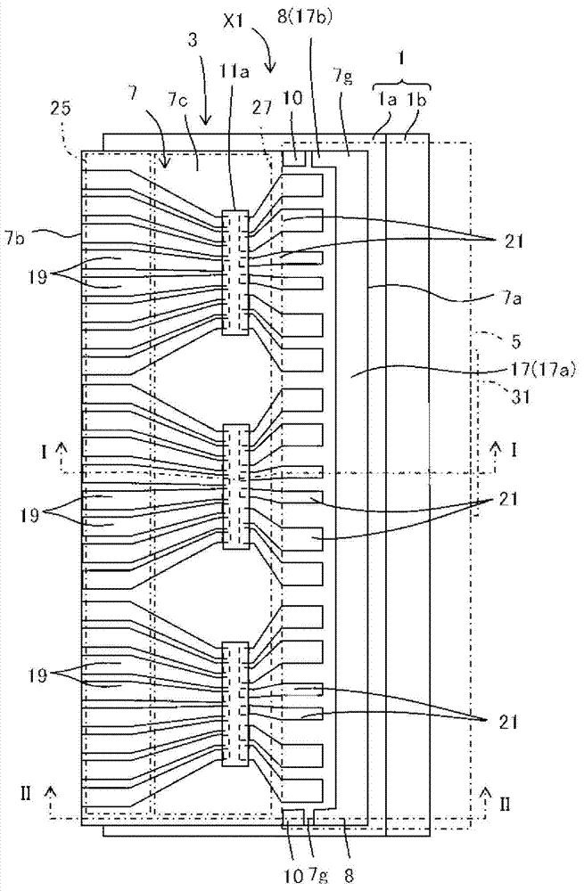
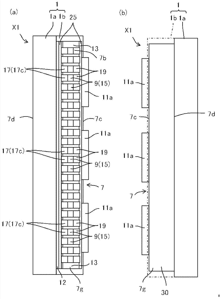
[0029] Such as Figure 1~5 As shown, the thermal head X1 according to the first embodiment includes: a radiator 1; a head base 3 disposed on the radiator 1; a flexible printed wiring board 5 (hereinafter, called FPC5). in addition, figure 1 The illustration of the FPC5 is omitted in , and the area where the FPC5 is disposed is indicated by a dashed-dotted line. figure 2 In (b), the projection part 1b of the radiator 1 is omitted and shown.
[0030] Such as Figure 1~5 As shown, the radiator 1 includes: a rectangular plate-shaped platform 1a in plan view; a protrusion 1b disposed on the upper surface of the platform 1a and extending along one long side of the platform 1a. . In addition, the radiator 1 may be constituted only by the plate-shaped platform portion 1a. The radiator 1 is made of a metal material such as copper or aluminum, a...
no. 2 approach
[0109] use Figure 9 A second embodiment of the present invention will be described.
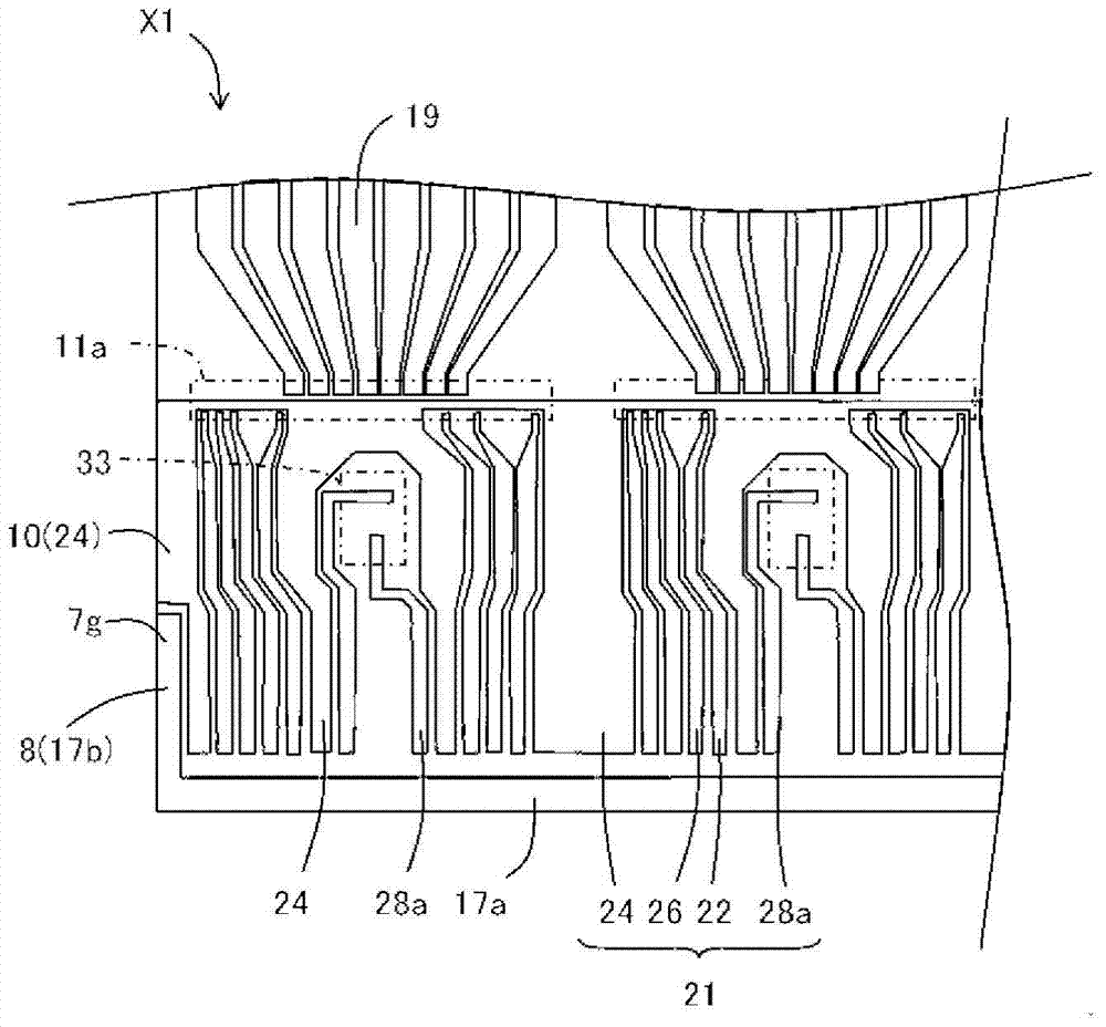
[0110] Figure 9 The shown thermal head X2 is provided with a second reinforcing member 10 at a portion surrounded by a two-dot chain line C. As shown in FIG. The IC-FPC connection electrode 21 is provided as the second reinforcing member 10 , and the IC electrode 22 , the ground electrode 24 , the IC control electrode 26 , and the temperature measurement electrode 28 a constitute the joining auxiliary member 12 as described above. Other structures are the same as those of the first embodiment.
[0111] In the second embodiment, the common electrode 17 is also provided on the edge portion 7 g of the substrate 7 . Therefore, the common electrode 17 serves as the first reinforcing member 8 and the ground electrode 24 serves as the bonding auxiliary member 12 , thereby improving the strength of the edge portion 7 g of the substrate 7 .
[0112] In the thermal head X2 according to the second...
no. 3 approach
[0121] Such as Figure 10 As shown, the thermal head X3 according to the third embodiment is provided with the protruding portion 16 protruding toward the ground electrode 24 side from the extension portion 17a of the common electrode 17 provided on the first main surface 7c. That is, it has a plurality of protrusions 16 protruding toward the IC-FPC connection electrodes 21 . Furthermore, a protruding portion 16 protruding from the extension portion 17a of the common electrode 17 provided on the first main surface 7c toward the temperature measuring electrode 28a to which the temperature measuring member 33 is attached is also provided. The protruding portion 16 protruding toward the temperature measuring electrode 28 a of the first electrode extends to a region where the temperature measuring member 33 is mounted so as to enter below the temperature measuring member 33 .
[0122] Such as Figure 10 As shown, the IC-FPC connection electrodes 21 connecting the driver IC 11a a...
PUM
 Abstract
Description
Claims
Application Information
 - R&D
- Intellectual Property
- Life Sciences
- Materials
- Tech Scout
- Unparalleled Data Quality
- Higher Quality Content
- 60% Fewer Hallucinations
Browse by: Latest US Patents, China's latest patents, Technical Efficacy Thesaurus, Application Domain, Technology Topic, Popular Technical Reports.
© 2025 PatSnap. All rights reserved.Legal|Privacy policy|Modern Slavery Act Transparency Statement|Sitemap|About US| Contact US: help@patsnap.com


