A thermal processing automatic cylinder clamping mechanism

A clamping mechanism and thermal processing technology, used in workpiece clamping devices, manufacturing tools, etc., can solve problems such as inability to achieve automatic cooling, short cylinder life, and side-to-side clamping of the clamp, achieving long life and reducing material loss costs. , the effect of improving work efficiency

Active Publication Date: 2015-12-09
CHINA RAILWAY LONGCHANG MATERIALS
View PDF10 Cites 0 Cited by
  • Summary
  • Abstract
  • Description
  • Claims
  • Application Information

AI Technical Summary

Problems solved by technology

[0003] (1) The diameter of the pin 10 used to fix the clamp 9 is generally only 10mm, and a 1mm thick copper sleeve is inlaid as a wear part. Because the diameter is too small and the contact surface is small, the clamp will shake from side to side after a period of use, and the grip unstable phenomenon
[0004] (2) The clamp 9 adopts an integral structure, and the clamping part needs to be replaced as a whole after wear and tear, which wastes materials
[0005] (3) Especially when used in automatic thermal processing, automatic cooling cannot be realized, the life of the cylinder is not long, and the heat will be transferred to other equipment, causing damage

Method used


Image

  • A thermal processing automatic cylinder clamping mechanism
  • A thermal processing automatic cylinder clamping mechanism
  • A thermal processing automatic cylinder clamping mechanism

Examples


Embodiment Construction

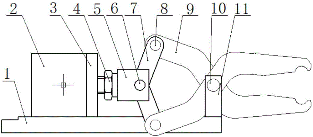
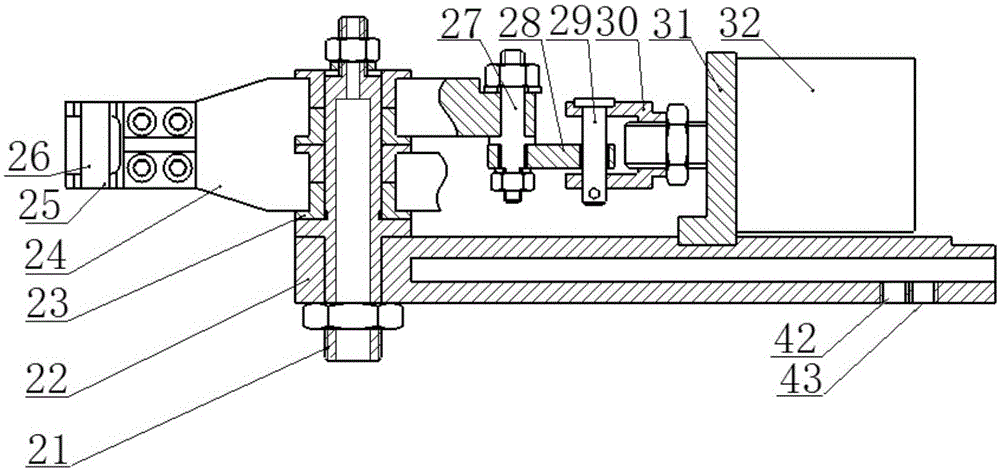
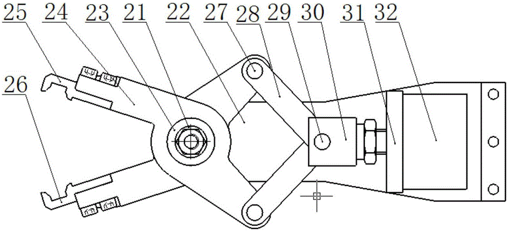
[0022] A thermal processing automatic cylinder clamping mechanism, such as figure 2 and image 3 As shown, it includes: main shaft 21, main support 22, bearing 23, rotating support 24, upper material clamp 25, lower material clamp 26, connection pins 27 and 29, connection block 28, connection seat 30, cylinder support 31, cylinder 32 etc., where:

[0023] The main shaft 21 and the cylinder support 31 are installed on the two ends of the main bracket 22 respectively, and the rotating bracket 24 is assembled on the main shaft 21 through the bearing 23; (In order to facilitate the replacement of the clip after wear, screw assembly can be used); the connection end of the rotating bracket 24 is connected to the connection block 28 through the connection pin 27; the connection block 28 is connected to the connection seat 30 through the connection pin 29; the connection seat 30 It is connected with the cylinder support 31, and the cylinder 32 is installed on the cylinder support 3...


PUM


Abstract

The invention discloses an automatic hot-working steam cylinder clamping mechanism. The automatic hot-working steam cylinder clamping mechanism comprises a spindle, a main support, a rotary support, a feeding clamp, a discharging clamp, a steam cylinder support and a steam cylinder, wherein the spindle and the steam cylinder support are mounted at two ends of the main support respectively, and the rotary support is assembled on the spindle through a bearing; the feeding clamp and the discharging clamp are mounted at two clamping ends of the rotary support respectively. The automatic hot-working steam cylinder clamping mechanism has the advantages that by application of the main aluminum alloy support with a cooling channel, the JFB solid inlaid graphite bearing and the asymmetric replaceable clamps, stability of the clamping mechanism is improved greatly, the clamping mechanism can run stably in high-temperature and high-dust-content severe environments and is long in service life and low in fault rate, working efficiency of automatic production is improved, and the fault rate is reduced.

Description

technical field [0001] The invention relates to a thermal processing automatic cylinder clamping mechanism. Background technique [0002] In automatic production, the cylinder clamping mechanism is often used. The structure of the existing cylinder clamping mechanism is as follows: figure 1 As shown, it includes: main bracket 1, cylinder 2, cylinder bracket 3, lock nut 4, cylinder connection seat 5, pin 6, connection block 7, pin 8, clamp 9, pin 10, clamp seat 11, etc. However, this mechanism has the following disadvantages: [0003] (1) The diameter of the pin 10 used to fix the clamp 9 is generally only 10mm, and a 1mm thick copper sleeve is inlaid as a wear part. Because the diameter is too small and the contact surface is small, the clamp will shake from side to side after a period of use, and the grip unstable phenomenon. [0004] (2) The clamp 9 adopts an integral structure, and the clamping part needs to be replaced as a whole after wear and tear, which wastes mate...

Claims


Application Information

Patent Timeline
Patent Type & Authority Patents(China)
IPC IPC(8): B25B11/00
CPCB25B11/00
Inventor 刘伟朱福林
Owner CHINA RAILWAY LONGCHANG MATERIALS
Why Eureka
Try Eureka