Injection mold with insert assembling structure

An injection mold and insert technology, applied in the coating and other directions, can solve the problems of insert coverage and complex structure, and achieve the effect of improving the qualification rate of plastic parts and improving production efficiency

Active Publication Date: 2014-02-26
昌辉汽车电器(黄山)股份公司
View PDF6 Cites 21 Cited by
  • Summary
  • Abstract
  • Description
  • Claims
  • Application Information

AI Technical Summary

Problems solved by technology

[0004] The purpose of the present invention is to provide an injection mold with an insert structure, which solves the problem that the previous injection mold with an insert structure has a complex structure and is prone to insert coverage

Method used


Image

  • Injection mold with insert assembling structure
  • Injection mold with insert assembling structure
  • Injection mold with insert assembling structure

Examples


Embodiment Construction

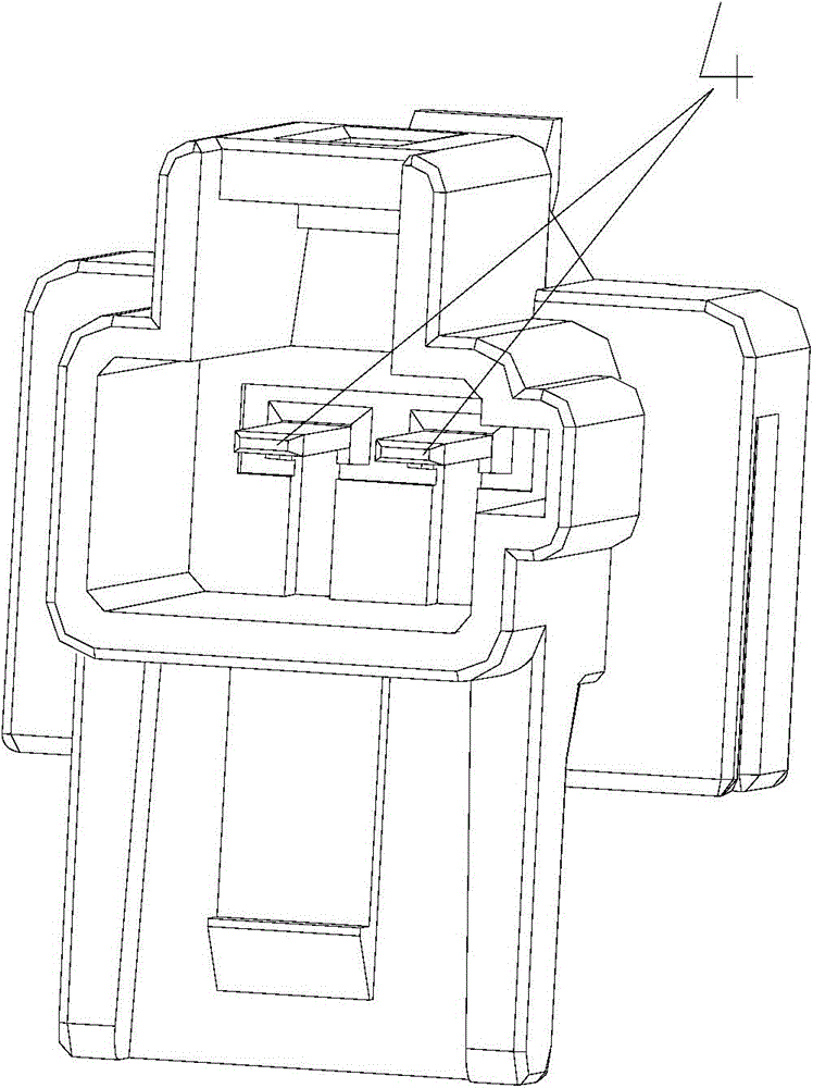
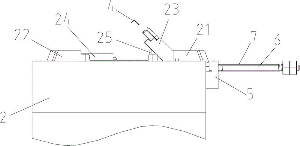
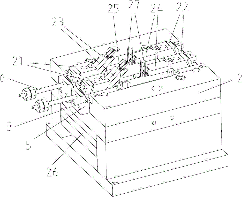
[0016] Examples, please refer to Figures 1 to 4 , an injection mold with an insert structure, including a fixed mold 1 and a movable mold 2, wherein the fixed mold 1 is equipped with a first slanted guide post 11 and a second slanted guide post 12, the first slanted guide post 11 and The second inclined guide column 12 is set in the shape of "eight"; the movable mold 2 is provided with a guide chute 3, and the first slider 21 and the second slider 22 are arranged in the guide chute 3; the first slider 21 is provided with a side core 23 for assembling the insert 4 and a first through hole matched with the first inclined guide post 11, and the second slider 22 is provided with a movable mold core 24 matched with the side core 23 And the second through hole matched with the second oblique guide post 12 .

[0017] Further, the movable mold 2 also includes a needle face plate 26 on which a group of unloading rods 27 is installed. The side core 23 is hinged to the first slider 21...


PUM


Abstract

An injection mold with an insert assembling structure includes a fixed mold (1) and a movable mold (2), and is characterized in that the fixed mold (1) is provided with a first inclined guide pillar (11) and a second inclined guide pillar (12), and the first inclined guide pillar (11) and the second inclined guide pillar (12) are arranged in a splayed shape; the movable mold (2) is provided with a guide sliding chute (3), and first sliding blocks (21) and second sliding blocks (22) are arranged in the guide sliding chute; the first sliding blocks (21) are each provided with a side drawing core (23) and a first through hole, the side drawing cores (23) are used for assembling inserts (4), and the first through hole is matched with the first inclined guide pillar (11); the second sliding blocks (22) are each provided with a movable mold core (24) and a second through hole, the movable mold cores (24) are matched with the side drawing cores (23), and the second through hole is matched with the second inclined guide pillar. The injection mold solves the problems that a conventional injection mold with an insert assembling structure has complex structure and easily produces insert coverage, and improves the production efficiency and the product qualification rate.

Description

technical field [0001] The invention belongs to the field of injection molds, in particular to an injection mold with an insert structure. Background technique [0002] Due to technical problems, the existing products cannot realize the molding of insert pins and plastic parts together, and the pins need to be assembled in a follow-up process. Since the pins are inserted later, the length of the pins is not uniform, and the pins are easy to fall off. Such as various types of automotive electrical switches, as shown in the accompanying drawings figure 1 shows the structure of plastic parts with metal inserts and metal inserts. Because the inserts are relatively thin and easy to deform, installation is difficult, and defects such as insert scrapping and insert covering are prone to occur. [0003] For example, Chinese patent application number 201120242447.1 discloses an insert assembly device for an injection mold, which is assembled on the inner and rear molds of the lower...

Claims


Application Information

Patent Timeline
Patent Type & Authority Applications(China)
IPC IPC(8): B29C45/33B29C45/14
CPCB29C45/33B29C45/4435
Inventor 王进丁王正成朱排进李宏志
Owner 昌辉汽车电器(黄山)股份公司
Why Eureka
Try Eureka