Flush piping system, oxygen generator and their respective control methods

A technology for flushing pipeline systems and pipelines, which is applied in the fields of flushing pipeline systems, oxygen generators and their respective control fields, which can solve the problems of excessive flushing of exhausted tanks, oxygen waste, etc., and avoid shutdown work, increase oxygen production, and avoid the effect of normally open through

Active Publication Date: 2015-10-21
ZHUHAI HOKAI MEDICAL INSTR +1
View PDF3 Cites 0 Cited by
  • Summary
  • Abstract
  • Description
  • Claims
  • Application Information

AI Technical Summary

Problems solved by technology

Since the flushing pipeline is straight and normally open, the exhausted tank is often over flushed, resulting in a waste of oxygen

Method used


Image

  • Flush piping system, oxygen generator and their respective control methods
  • Flush piping system, oxygen generator and their respective control methods
  • Flush piping system, oxygen generator and their respective control methods

Examples


Embodiment Construction

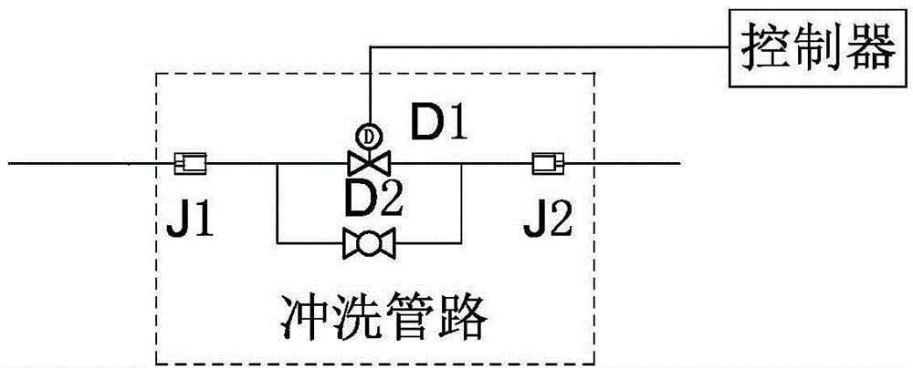
[0042] Such as figure 2 As shown, the flushing pipeline system includes the controller and the flushing pipeline. The flushing pipeline includes the first throttle J1, the electronically controlled adjustable valve D1, and the second throttle J2 connected in sequence from left to right. A manual adjustable valve D2 is connected between the two ends of the adjustable valve D1; the controller is connected to the electrically controlled adjustable valve D1. The manual adjustable valve D2 is convenient for manual adjustment when the electronically controlled adjustable valve D1 is not working normally; when the electronically controlled adjustable valve D1 is working normally, the manually adjustable valve D2 is in the closed state.

[0043] The electrically controlled adjustable valve D1 can be an angle seat solenoid valve or a pilot solenoid valve or a digital regulating valve or a proportional valve or other two-way solenoid valves.

[0044] The flushing pipeline system is ma...


PUM


Abstract

The invention relates to a flushing pipeline system, an oxygenerator and respective control methods thereof, wherein, the flushing pipe-line system comprises a controller and a flushing pipeline, and the flushing pipeline comprises electric control adjustable valves connected in series connection and at least one restrictor, and the controller controls connection of the electric control adjustable valves. The flushing pipeline system is good for improving oxygen output of the oxygenator, and is convenient for shortening time from temporary shutdown to normal work of the oxygenator.

Description

【Technical field】 [0001] The invention relates to a flushing pipeline system, an oxygen generator and their respective control methods. 【Background technique】 [0002] Currently, the oxygen generators on the market include the first tank A, the second tank B, the first intake valve DA2, the second intake valve DB2, the first exhaust valve DA1, the second exhaust valve DB1, the first Muffler X1, second muffler X2, balance valve P1, flushing pipeline, first throttle J1, second throttle J2, first outlet valve C1, second outlet valve C2, main outlet valve V2; flushing pipeline , including the first restrictor J1 and the second restrictor J2 connected sequentially from left to right; the inside of the first tank A and the second tank B are equipped with molecular sieves; the intake end of the first tank A communicates with the first The outlet of the intake valve DA2 and the inlet of the first exhaust valve DA1, the outlet of the first exhaust valve DA1 is connected to the inlet...

Claims


Application Information

Patent Timeline
Patent Type & Authority Patents(China)
IPC IPC(8): C01B13/02
Inventor 田助明
Owner ZHUHAI HOKAI MEDICAL INSTR
Why Eureka
Try Eureka