Supercharge Your Innovation With Domain-Expert AI Agents!

A bonding method for a hyperboloid reflective mirror of a sunlight collector for solar thermal power generation

A solar thermal power generation and collector technology, which is applied in the field of solar thermal power generation, can solve the problems that the surface accuracy of the hyperboloid reflector cannot meet the surface profile accuracy, the processing efficiency is low, and the investment cost of the molding die is high.

Active Publication Date: 2015-12-30
AECC AVIATION POWER CO LTD
View PDF4 Cites 0 Cited by
  • Summary
  • Abstract
  • Description
  • Claims
  • Application Information

AI Technical Summary

Problems solved by technology

Compression molding requires a dedicated large press and up and down molds, and the mold structure is complex
Thermoforming technology is suitable for forming reflectors with thicker glass thickness, which requires high-temperature heating equipment and thermoforming molds, and the surface accuracy of thermoformed hyperboloid reflectors cannot meet the surface accuracy requirements of solar collector reflectors for solar thermal power generation
In addition, the above two methods have high investment costs for equipment and molding dies, and low processing efficiency.

Method used


Image

  • A bonding method for a hyperboloid reflective mirror of a sunlight collector for solar thermal power generation
  • A bonding method for a hyperboloid reflective mirror of a sunlight collector for solar thermal power generation

Examples


Embodiment 1

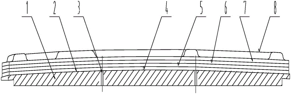
[0015] Example 1, the reflective lens with the smallest area, the outer dimension is 1480mmx815mm, the outer dimension of the bonding mold 1 is 3mm wider than the outer outline of the reflective lens by 3mm, vacuumize to -0.1MPa, heat to 120°C, keep warm for 1h and then follow the furnace Cool to room temperature. Bond the metal back plate 8 and let it stand at room temperature for at least 6 hours. After bonding and molding on the bonding mold 1, the hyperboloid profile of the mirror paraboloid is within 0.9 mm, and the diameter of the focused spot is less than 140 mm, and one piece is bonded every 10 hours. At the same time, 4 sets of bonding molds are used for processing, and 8 pieces can be bonded every 24 hours.

Embodiment 2

[0016] Example 2, a reflective lens with a small area, the outer dimension is 1464mmx922mm, the outer dimension of the bonding mold 1 is 4mm wider than the outer outline of the reflective lens by 4mm, vacuumize to -0.1MPa, heat to 130°C, keep warm for 1h and then The furnace was cooled to room temperature. Bond the metal back plate 8 and let it stand at room temperature for at least 6 hours. After bonding and forming on the bonding mold 1, the hyperboloid profile of the mirror paraboloid is within 1 mm, and the diameter of the focused spot is less than 150 mm, and one piece is bonded every 10 hours. At the same time, 8 sets of bonding molds are used for processing, and 16 pieces can be bonded every 24 hours.

Embodiment 3

[0017] Example 3, the reflective lens with the largest area, the outer dimension is 1440mmx1344mm, the outer dimension of the bonding mold 1 is 8mm wider than the outer outline of the reflective lens by 8mm, vacuumize to -0.08MPa, heat to 140°C, keep warm for 1.5h and then The furnace was cooled to room temperature. Bond the metal back plate 8 and let it stand at room temperature for at least 8 hours. After bonding and forming on the bonding mold 1, the hyperboloid profile of the mirror parabola is within 1.3 mm, and the diameter of the focused spot is less than 180 mm, and one piece is bonded every 16 hours. At the same time, 4 sets of bonding molds are used for processing, and 4 pieces can be bonded every 24 hours.


PUM


Abstract

The invention belongs to the technology of solar thermal electric power generation, and particularly relates to improvement of a method for bonding a hyperboloid reflector of a sunlight collector for solar thermal electric power generation. The method comprises steps of preparing a bonding die, bonding a reflector (4) with a metal lining plate (5), and bonding the metal lining plate (5) with a metal back plate (8). The molded surface accuracy and bonding efficiency of the reflector of the sunlight collector for solar thermal electric power generation are sharply improved, the method is simple, and the manufacture cost of the reflector is reduced.

Description

technical field [0001] The invention belongs to the technical field of solar thermal power generation, and relates to an improvement of a bonding method for a reflective mirror of a sunlight collector used for solar thermal power generation. Background technique [0002] At present, compression molding or thermoforming techniques are commonly used for large hyperboloid mirrors. Compression molding requires a dedicated large-scale press and an up-and-down pattern forming mold, and the mold structure is complex. Thermoforming technology is suitable for forming reflectors with thick glass thickness, which requires high-temperature heating equipment and thermoforming molds, and the surface accuracy of thermoformed hyperboloid reflectors cannot meet the surface accuracy requirements of solar collector reflectors for solar thermal power generation. In addition, the above two methods have high equipment and molding die input costs and low processing efficiency. Invention content...

Claims


Application Information

Patent Timeline
Patent Type & Authority Patents(China)
IPC IPC(8): C03C27/00
Inventor 李宏超徐志伟李浩张文佟兆全王建穆元春
Owner AECC AVIATION POWER CO LTD
Features
  • R&D
  • Intellectual Property
  • Life Sciences
  • Materials
  • Tech Scout
  • Unparalleled Data Quality
  • Higher Quality Content
  • 60% Fewer Hallucinations
Learn More