Fiber grating sensor packaging device for measuring support and hanger pull rod strain

A fiber grating and packaging device technology, applied in the field of strain sensors, can solve the problems of being easily damaged by external forces and affected by the external environment

Inactive Publication Date: 2014-02-26
TIANJIN UNIV
View PDF8 Cites 16 Cited by
  • Summary
  • Abstract
  • Description
  • Claims
  • Application Information

AI Technical Summary

Problems solved by technology

The conventional fiber grating sensor pastes the FBG directly on the test point of the test piece. This method has the advantages of simple operation, can observe and control the damage of the FBG during the assembly process, and is easy to replace the damaged sensor, but the disadvantage is that it is easy to be damaged. Damaged by external forces and affected by the external environment

Method used


Image

  • Fiber grating sensor packaging device for measuring support and hanger pull rod strain
  • Fiber grating sensor packaging device for measuring support and hanger pull rod strain
  • Fiber grating sensor packaging device for measuring support and hanger pull rod strain

Examples


Embodiment Construction

[0014] The technical solutions of the present invention will be further described in detail below in conjunction with specific embodiments.

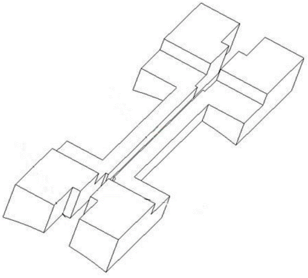
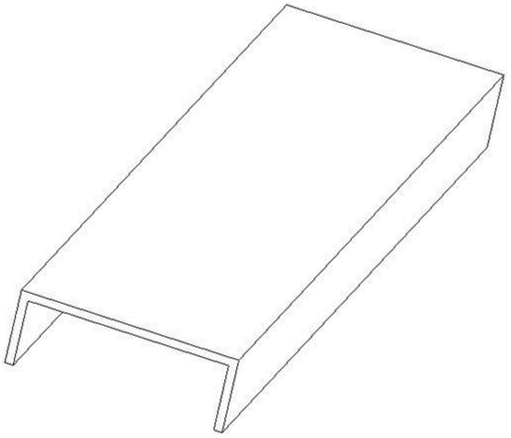
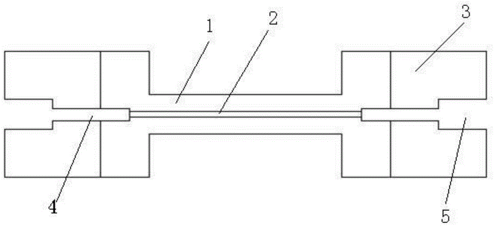
[0015] attached by figure 1 As shown in -4, 1 is an intermediate part, 2 is a bare grating area, 3 is an end part, 4 is an optical fiber area, and 5 is an optical fiber clamp area. The packaging device of the present invention is composed of a base and a cover. The cover is arranged above the base to protect and isolate the base. The base is composed of two clamping parts symmetrically arranged on the left and right. The two The clamping parts are connected as a whole through the arc bottom surface.

[0016] The clamping part is composed of end parts 3 arranged at both ends and an intermediate part 1 arranged in the center, and a bare grating area 2 is arranged between the two symmetrically arranged clamping parts. An optical fiber section 4 is provided at both ends of the optical fiber section, and an optical fiber clamp section 5 is ...


PUM


Abstract

The invention discloses a fiber grating sensor packaging device for measuring support and hanger pull rod strain. The device is formed by a base and a cover plate. The base is formed by two clamping components which are symmetrically arranged at left and right sides. The two clamping components are connected to be a whole body through an arc bottom face. Each of the clamping components is formed by end parts arranged at two ends and a center part arranged in the middle. A bare grating area is arranged between the two clamping components which are symmetrically arranged at left and right sides. Two ends of the bare grating area are provided with fiber areas. The other end of each of the fiber areas is provided with a fiber clamp area. According to the technical scheme of the invention, in order to raise the fitness of a fiber grating sensor pull rod, the base is designed to be a circular arc surface which is matched with the curve of a fixed position, in the process of packaging, the fiber grating is placed into the bare fiber area and the fiber areas and is clamped tightly through fiber clamps, an instantaneous drying adhesive is used to fix a fiber position to be tightly attached with a package base, an epoxy resin adhesive is used for permanent fixation, and finally a cover plate and the base are bonded to be a whole body.

Description

technical field [0001] The invention belongs to the field of strain sensors, and relates to a packaging device for protecting optical fiber gratings, in particular to a grating optical fiber packaging device for measuring the strain of a round rod member. Background technique [0002] At present, thermal power generation occupies a dominant position in my country's power industry. Due to its high power generation efficiency and low energy consumption, ultra-supercritical thermal power generating units have gradually become the mainstream trend of generating units. Debugging puts higher demands on it. As the pipeline transportation system of the ultra-supercritical unit, the steam pipeline has very strict requirements for installation, commissioning and monitoring during service due to its important position. The study found that the service state of the support and hanger used to fix the steam pipeline in the generator set has a great influence on the stress distribution of ...

Claims


Application Information

Patent Timeline
Patent Type & Authority Applications(China)
IPC IPC(8): G01B11/16
Inventor 徐连勇李蒙韩永典荆洪阳
Owner TIANJIN UNIV
Why Eureka
Try Eureka