Intelligent Remote Sensing Microspace Optical Device Rotation Positioning System

A technology of optical devices and positioning systems, applied in the field of remote sensing positioning systems, can solve the problems of not providing a placement location, not supporting automatic replacement of multiple samples or temporarily inserting a component, and difficult placement of instruments

Inactive Publication Date: 2017-01-11
BEIJING UNIV OF TECH
View PDF5 Cites 0 Cited by
  • Summary
  • Abstract
  • Description
  • Claims
  • Application Information

AI Technical Summary

Problems solved by technology

During the experiment, we found that the sample cavity of many instruments does not support the automatic replacement of multiple samples or the temporary insertion of a component, but if an automatic sample change system is added or a component is inserted, the instrument itself does not have a corresponding fixed space. , and second, if upgrading the system requires more space and funds
For example, the minimum light intensity of all spectrometers is basically fixed when the instrument leaves the factory. If a lower light intensity is required, we need to artificially add an attenuation sheet. However, the instrument itself does not provide a placement position and support point. If you add another optical bracket, some instruments will be difficult to place due to space constraints, and it is also very inconvenient for people to adjust in a small space.

Method used


Image

  • Intelligent Remote Sensing Microspace Optical Device Rotation Positioning System
  • Intelligent Remote Sensing Microspace Optical Device Rotation Positioning System
  • Intelligent Remote Sensing Microspace Optical Device Rotation Positioning System

Examples


Embodiment Construction

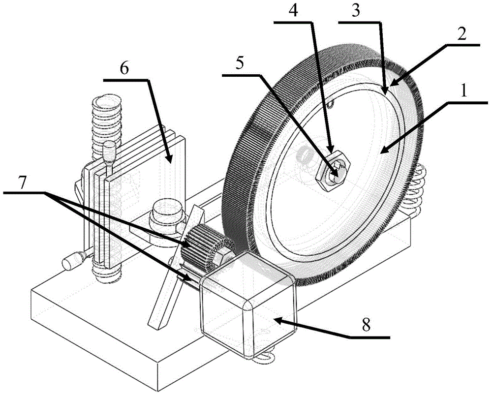
[0040] Combine below figure 1 The present invention is described further:

[0041] The intelligent remote sensing micro-space optical device rotation positioning system combines a mechanical system and an intelligent control system. Realize the positioning or rotation operation for the newly inserted components in the existing instrument. Reasonable use of the existing space of the instrument, thereby expanding the practical range of the instrument. Ultimately, it can broaden applications, save space, and improve efficiency.

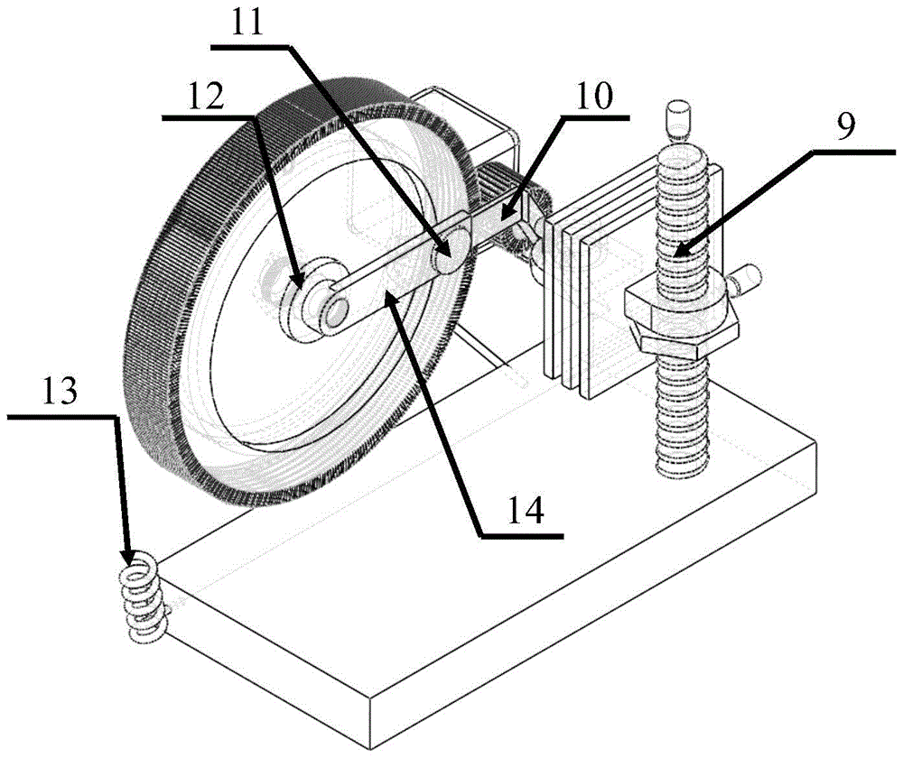
[0042] Such as figure 1 and figure 2The shown rotating positioning system for intelligent remote sensing micro-space optical devices includes an optical element rotating frame 2 for assembling and rotating the optical element 1; an optical element fixing rubber ring 3 and an optical element fixing sleeve 12 for fixing the optical element 1 to prevent the device from slipping out The fastening nut 4 and the fastening screw 11 of the fixed bracket ...


PUM


Abstract

The utility model relates to a remote sensing positioning system generally suitable for placing optical devices in an optical system, which belongs to the application fields of optical devices, mechanical parts and automatic instruments and meters. The present invention includes: an optical element rotating frame 2 for assembling and rotating the optical element 1; an optical element fixing rubber ring 3 and an optical element fixing sleeve 12 for fixing the optical element 1 to prevent it from slipping out; and for tightening the fixing bracket during assembly Nut 4 and tightening screw 11; optical element rotating frame rotating shaft 5 and its fixed part optical element rotating frame rotating shaft support 14; two-dimensional fine-tuning translation platform 6 for realizing plane fine-tuning and system bracket 9 for height positioning; reduction gear for realizing low-speed rotation Group 7 and its fixing parts: reduction gear set fixed bracket 10; motor 8 providing rotational power; remote signal processing terminal 13 and remote control terminal 15. The invention aims at different instruments, through reasonable assembly and placement, can realize the fixation and rotation of optical elements inserted as required, and is convenient to use and improves efficacy.

Description

technical field [0001] The invention relates to a remote sensing positioning system generally suitable for placing optical devices in an optical system, belonging to the application fields of optical devices, mechanical parts and automatic instruments. Background technique [0002] With the continuous progress and development of science and technology, the emergence of integrated circuits, the invention of lasers, the application of optoelectronic devices, and the development of robotics have all provided great help for human beings to explore this survivable world. Before the integrated circuit appeared, the computer still needed to occupy a huge space; before the laser was invented, taking a Raman spectrum required several months of exposure; At that time, people risked their lives to explore deeper seas and deeper wells... Our safe, peaceful, efficient and convenient life is all thanks to the continuous development of science and engineering technology. The emergence of ...

Claims


Application Information

Patent Timeline
Patent Type & Authority Patents(China)
IPC IPC(8): G02B7/00
Inventor 王丽甘渝林王荣平苏雪琼
Owner BEIJING UNIV OF TECH
Why Eureka
Try Eureka