
A coded optical modulation disc with improved resolution

A technology of coded light and modulation disk, which is applied in the direction of converting sensor output, measuring device, instrument, etc., can solve the problems of low resolution, few number of modulation disk codes, and aliasing at the crossover point. The effect of the cutoff point continuation

Active Publication Date: 2016-06-22
CHANGCHUN SHIKAI TECH IND CO LTD
View PDF5 Cites 0 Cited by
  • Summary
  • Abstract
  • Description
  • Claims
  • Application Information

AI Technical Summary

Problems solved by technology

[0006] The main problem of the modulation disc is that the cut-off point of the scanning code of the modulated light received by the laser receiver is the intersection point of two sets of codes, and aliasing is prone to occur at the intersection point; Resolution, the number of coded modulation discs is less, the resolution is low, and ultimately affects the guidance accuracy

Method used


Image

  • A coded optical modulation disc with improved resolution
  • A coded optical modulation disc with improved resolution
  • A coded optical modulation disc with improved resolution

Examples


Embodiment Construction

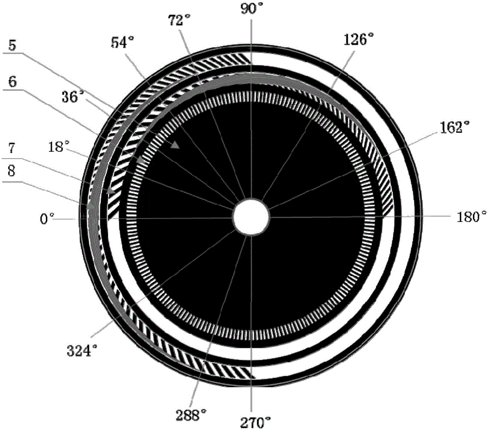
[0014] The invention according to figure 2 The structure shown is implemented, wherein the material of the substrate 5 is made of K9 optical glass through optical cold processing, the surface is chrome-plated, and the circular grating 6, four sets of codes in the inner code track 7 and four sets of codes in the outer code track 8 appear. 20 pairs and 35 pairs are adopted for the encoding on both sides of the inner code track 7, and 25 pairs and 35 pairs are adopted for the encoding on both sides of the outer code track 8. In inner code track 7 and outer code track 8, two groups of filling codes press image 3 In the implementation of the structure shown, the third group and the fourth group of codes filled in the inner code track 7 adopt 5 pairs and 6 pairs of black and white and parallel codes respectively, and the third group and the fourth group codes filled in the outer code track 8 are respectively Use 5 pairs and 6 pairs of black and white and parallel codes.


PUM


Abstract

The invention discloses a coded optical modulation disc with improved resolution, which belongs to a dimming device involved in the technical field of photoelectric guidance. The technical problem to be solved is to provide a coded optical modulation disc with improved resolution. The technical solutions to be solved include substrate, circular grating, inner code track and outer code track. The circular grating is located at the innermost circle of the light modulation disc. The coding of the inner and outer code tracks all accounts for 180°, and the starting point of the inner code track and the starting point of the outer code track differ by 90°. Both the inner and outer code tracks adopt four sets of codes, and each pair of coded planes in each group is parallel to each other and equally spaced straight lines after being unfolded. The first group of 20 pairs of codes is used at the starting point of the inner code track, and the second group of 35 pairs of codes is used at the end point. The third group of 5 pairs and the fourth group of 6 pairs of codes are filled in the track gap clockwise. The cut-off points of the two groups of codes filled in the middle of the two code tracks of the optical modulation disc are continuous, and the guidance precision is high.

Description

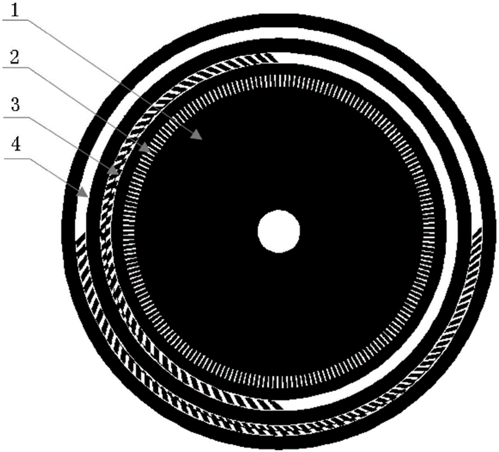
technical field [0001] The invention belongs to the technical field of photoelectric guidance and relates to a coding dimming device with improved resolution. Background technique [0002] The so-called optical modulation disc is a modulating optical device that encodes and modulates the light beam in the optical path to generate a continuously modulated optical signal. It is mostly used in the field of optical guidance technology, and is widely used in the field of science and technology and industry. [0003] The existing technology closest to the present invention is a patent applied by Changchun Shikai Technology Industry Co., Ltd. in 2010, patent number: 20101022259525, patent name: a kind of oblique code optical modulation disc, such as figure 1 shown. It includes substrate 1, circular grating 2, inner code track 3 and outer code track 4. [0004] Chromium is plated on the substrate 1, and the circular grating 2, the inner code track 3 and the outer code track 4 are ...

Claims


Application Information

Patent Timeline
Patent Type & Authority Patents(China)
IPC IPC(8): G01D5/347
Inventor 徐椿明戴威威李娜王继奎郭敏
Owner CHANGCHUN SHIKAI TECH IND CO LTD
Learn More