A detection method for types of cookers and an electromagnetic heating apparatus

A technology of electromagnetic heating device and detection method, which is applied in the detection of pot type and the field of electromagnetic heating device, and can solve the problems such as difficult to realize electromagnetic heating treatment

Active Publication Date: 2014-02-26
MIDEA GRP CO LTD +1
View PDF5 Cites 43 Cited by
  • Summary
  • Abstract
  • Description
  • Claims
  • Application Information

AI Technical Summary

Problems solved by technology

[0002] Since ferromagnetic metals have higher energy conversion efficiency in the process of electromagnetic heating, most of the electromagnetic heating devices in the related art only support the working mode suitable for heating ferromagnetic pans. As far as magnetic cookware is concerned, it is difficult to achieve normal electromagnetic heating treatment

Method used


Image

  • A detection method for types of cookers and an electromagnetic heating apparatus
  • A detection method for types of cookers and an electromagnetic heating apparatus
  • A detection method for types of cookers and an electromagnetic heating apparatus

Examples


Embodiment 1

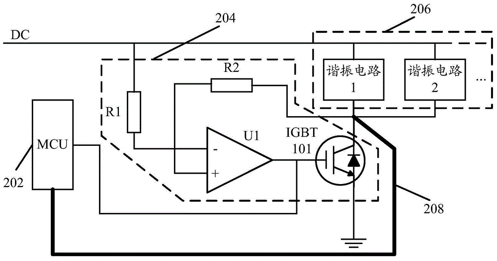
[0120] image 3 for figure 2 A schematic diagram of the circuit structure of an implementation mode of the illustrated embodiment.

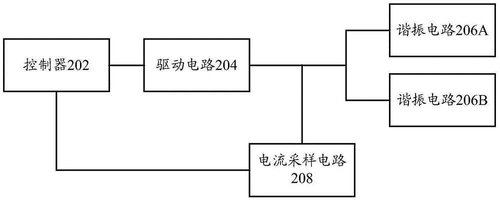
[0121] Such as image 3 As shown, the resonant circuit 206 includes a resonant circuit 1, a resonant circuit 2, etc., corresponding to figure 2 Resonant circuit 206A and resonant circuit 206B are shown, among others.

[0122] Taking the resonant circuit 1 as an example, its first end is connected to a DC power supply, and its second end is connected to the collector of the IGBT101 in the driving circuit 204; the driving circuit 204 includes a resistor R1, a resistor R2 and a comparator U1, wherein the resistor R1 One end of resistor R2 is connected to the above-mentioned DC power supply, the other end is connected to the inverting end of comparator U1, one end of resistor R2 is connected to the second end of resonant circuit 1, and the other end is connected to the non-inverting end of comparator U1, comparator U1 The output terminal of is ...

Embodiment 2

[0129] Figure 4A for figure 2 A schematic diagram of the circuit structure of an implementation mode of the illustrated embodiment.

[0130] Such as Figure 4A As shown, the controller 202 may specifically be an MCU.

[0131] Specifically, the driving circuit 204 can realize the driving control of the resonant circuit 206 under the control of the MCU through the IGBT201, the IGBT202 and the corresponding IGBT control chips U102, U103, etc.

[0132] Among them, one end of the IGBT control chip U102 is connected to the MCU, and the other end is connected to the gate of the IGBT201, and the collector of the IGBT201 receives the AC signal input by the PFC power supply; one end of the IGBT control chip U103 is connected to the MCU, and the other end is connected to the IGBT202 The gate of the IGBT202 is connected to the emitter of the IGBT201, and the electrical signal is output to the resonant circuit 206.

[0133] The resonant circuit 206 specifically includes: an inductor ...


PUM


Abstract

The invention provides a detection method for types of cookers. The detection method for the types of the cookers comprises the following steps: any one of a first resonance circuit corresponding to ferromagnetic cookers or a second resonance circuit corresponding to non ferromagnetic cookers in an electromagnetic heating apparatus is switched on, and electromagnetic heating testing is carried out on a present cooker; in the process of the electromagnetic heating testing, current sampling is carried out on the switched-on resonance circuit; if an obtained first sampling current is matched with a first standard corresponding to the switched-on resonance circuit, the cooker is determined to be a cooker of the type corresponding to the switched-on resonance circuit. The invention also brings forward the electromagnetic heating apparatus. Through the technical scheme of the present invention, the types of the cookers which need to be subjected to electromagnetic heating can be accurately determined, so that through selecting an appropriate heating, so that the electromagnetic heating carried out on metal cookers of various types can be realized.

Description

technical field [0001] The invention relates to the technical field of electromagnetic heating, in particular to a method for detecting the type of a pot and an electromagnetic heating device. Background technique [0002] Since ferromagnetic metals have higher energy conversion efficiency in the process of electromagnetic heating, most of the electromagnetic heating devices in the related art only support the working mode suitable for heating ferromagnetic pans. As far as magnetic cookware is concerned, it is difficult to achieve normal electromagnetic heating treatment. [0003] However, there are various types of pots on the market, including many non-ferromagnetic pots (such as aluminum pots, copper pots, etc.), and there is a demand for electromagnetic heating of non-ferromagnetic pots. However, due to the property difference between the ferromagnetic pan and the non-ferromagnetic pan, it is necessary to use different methods for heating the ferromagnetic pan and the n...

Claims


Application Information

Patent Timeline
Patent Type & Authority Applications(China)
IPC IPC(8): H05B6/02H05B6/06
Inventor 冯江平王开祥李新峰陈敏梁为磊李昌
Owner MIDEA GRP CO LTD
Why Eureka
Try Eureka