Ball friction type mechanical clutch

A mechanical clutch, friction type technology, applied in the field of clutch, can solve the problems of large friction loss, large external size, the inability of the driving shaft and the driven shaft to rotate synchronously, etc., to achieve large transmission torque, simple and economical manufacturing, and easy replacement. Effect

Inactive Publication Date: 2014-03-05
HARBIN ENG UNIV
View PDF5 Cites 3 Cited by
  • Summary
  • Abstract
  • Description
  • Claims
  • Application Information

AI Technical Summary

Problems solved by technology

In the process of clutching and slipping, the driving shaft and the driven shaft cannot rotate synchronously, resulting in large wear and large dimensions.

Method used


Image

  • Ball friction type mechanical clutch
  • Ball friction type mechanical clutch
  • Ball friction type mechanical clutch

Examples


Embodiment Construction

[0028] The present invention will be described in more detail below with examples in conjunction with the accompanying drawings.

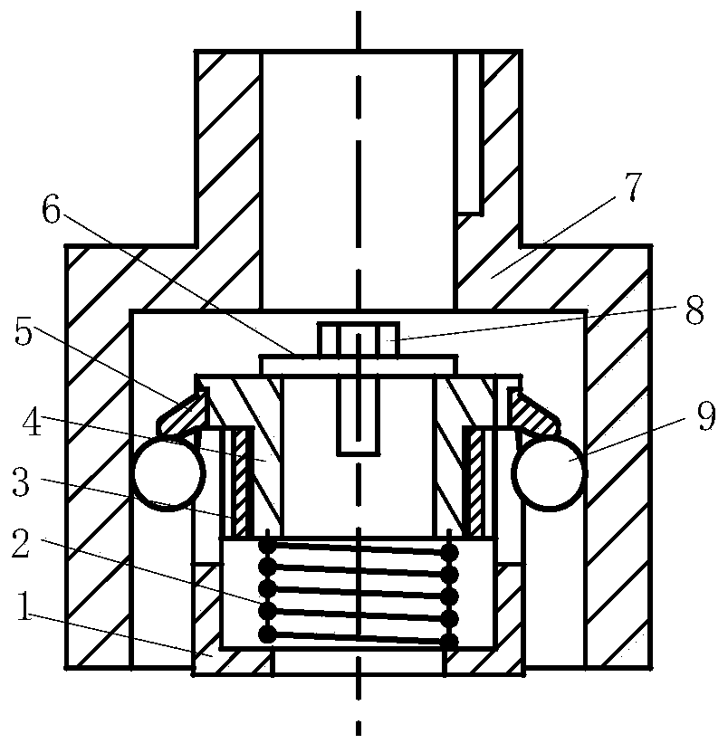
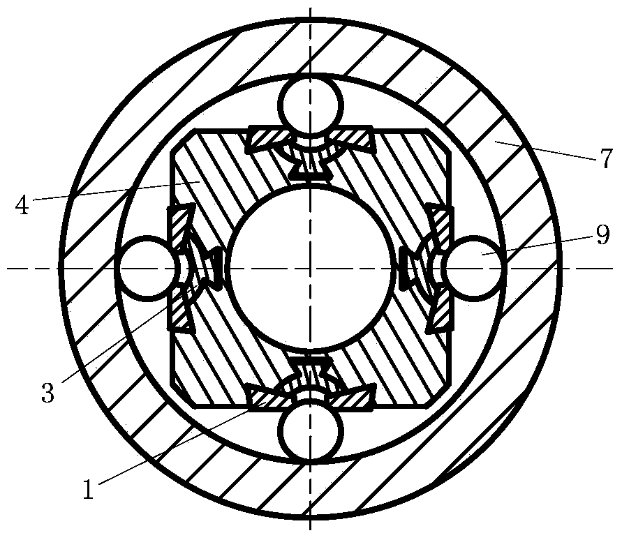
[0029] combine Figure 1-Figure 6 , the ball friction clutch of the present invention is made of ball friction clutch by outer casing 7, inner frame assembly, shift fork 1, ball 9, return spring 3, and wherein inner frame assembly is made of inner frame 4, ball baffle plate 5, strong magnet 3. Backing plate 6 and self-locking bolt 8 are formed. Embodiments of the present invention will be described below in conjunction with the accompanying drawings.

[0030] There are dovetail-shaped slots on the inner frame 4 ( image 3 ), combined with figure 1 , The ball baffle 5 and the strong magnet 3 are directly embedded on the inner frame 4 through the dovetail seat. Pass the shaft through the 4 shaft holes of the inner frame, connect the inner frame assembly and the driven shaft through the flat key, the backing plate 6 and the self-locking bolt 8, t...


PUM


Abstract

The invention provides a ball friction type mechanical clutch. The ball friction type mechanical clutch comprises an outer shell, an inner frame assembly, a ball, a reset spring and a shifting fork. The inner frame assembly is composed of an inner frame, a ball baffle and a strong magnet. A slot and a dovetail-shaped slot are formed in the inner frame, wherein the slot is matched with the shifting fork, and the dovetail-shaped slot is used for allowing the ball baffle and the strong magnet to be installed. The ball baffle and the strong magnet are directly embedded into the dovetail-shaped slot in the inner frame through a dovetail-shaped base, the ball is arranged on the strong magnet and limited by the ball baffle, the reset spring is installed between the shifting fork and the inner frame, the shifting fork is inserted into the slot of the inner frame, and the inner frame assembly and the ball are jointly arranged in the outer shell. The ball friction type mechanical clutch is large in transmission torque, capable of resisting impact, and suitable for working occasions where frequent temporary joint exists.

Description

technical field [0001] The invention relates to a clutch, in particular to a friction mechanical clutch. Background technique [0002] Due to the need for starting and stopping of mechanical equipment, clutches are commonly used in transmission systems. The clutch realizes the equipment stop, start and gear shift functions by cutting off and combining the power system and the transmission system. At present, the commonly used clutches mainly include pneumatic, mechanical, hydraulic, and electromagnetic clutches. Among them, mechanical clutches mainly include meshing and friction clutches, and commonly used friction clutches mainly include disc clutches and cone clutches. The friction clutch engages smoothly, even at high speed, the clutch is also very stable, but the transmission torque is small, and the working plane slips when overloaded, so it has the function of overload protection. In the process of clutching and slipping, the driving shaft and the driven shaft cannot...

Claims


Application Information

Patent Timeline
Patent Type & Authority Applications(China)
IPC IPC(8): F16D13/14F16D13/22
Inventor 史冬岩罗祥程秦峥嵘宋经远王青山
Owner HARBIN ENG UNIV
Why Eureka
Try Eureka