High-speed disc gear non-shaft loading rolling and unrolling device

A technology for rewinding and unwinding of rolls and gears, which is applied in the directions of winding strips, thin material handling, transportation and packaging, etc. It can solve the problems of short service life of spare parts, high structural complexity, and high labor intensity of workers, and achieve transmission torque The effect of large size, reduced precision of parts and compact structure

Active Publication Date: 2020-01-24
广东汕樟轻工股份有限公司
View PDF7 Cites 8 Cited by
  • Summary
  • Abstract
  • Description
  • Claims
  • Application Information

AI Technical Summary

Problems solved by technology

At present, there are some problems in the unwinding devices on the market, which need to be solved urgently, such as: shaking and sliding are unavoidable during the working process, which requires a lot of manual intervention, labor intensity of workers is high, and the structure is complicated. Short service life and other problems, so we make improvements to this, and propose a high-speed disk gear shaftless loading and unwinding device

Method used


Image

  • High-speed disc gear non-shaft loading rolling and unrolling device
  • High-speed disc gear non-shaft loading rolling and unrolling device
  • High-speed disc gear non-shaft loading rolling and unrolling device

Examples


Embodiment

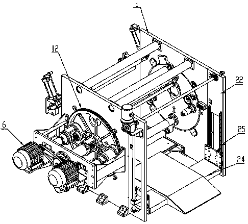
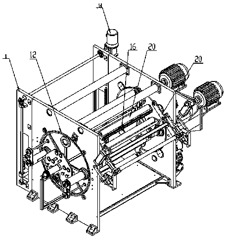
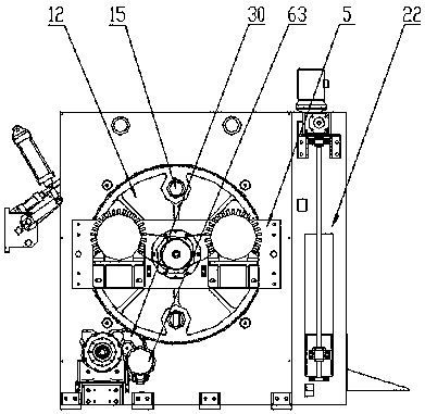
[0036] Example: such as Figure 1-7 As shown, a high-speed disc gear shaftless loading and unwinding device of the present invention includes:

[0037] The mounting frame is composed of wall panels 1 on both sides, an upper beam 2 and a lower beam 3, the upper beam 2 and the lower beam 3 are arranged between the wall panels 1 on both sides, and the bottom of the wall panels 1 is provided with a support base plate 4, A motor mounting frame 5 is arranged on the outside of one side of the wall panel 1;

[0038] Transmission mechanism, the transmission mechanism is composed of two motors 6, main transmission rod 7, two non-cylinder cone plug telescopic mechanisms 8 and two tensioning wheels 9, the two motors 6 are symmetrically installed on the outside of the motor mounting frame 5, the main transmission The rod 7 runs through the middle of the motor mounting frame 5, and the two motors 6 are connected to the main transmission rod 7 through the motor pulley 10. The transmission ...


PUM


Abstract

The invention discloses a high-speed disc gear non-shaft loading rolling and unrolling device which comprises an installation frame, a transmission mechanism, an overturning mechanism, a cutting mechanism and an unrolling lifting mechanism, wherein the transmission mechanism, the overturning mechanism, the cutting mechanism and the unrolling lifting mechanism are installed on the installation frame. Multi-stage transmission of a worm gear reduction motor and a disc large gear is adopted for the overturning mechanism, and a non-shaft loading structure is adopted for the device. By means of thehigh-speed disc gear non-shaft loading rolling and unrolling device, multi-stage transmission of the worm gear reduction motor and the disc large gear is adopted for the overturning mechanism, the transmission torque is large, rigidity is good, the braking capability is high, the problems of jittering, sliding and the like cannot happen in the high-speed material collecting and releasing process,the overturning material changing process and the cutting process of the equipment, and stable running is ensured; and the non-shaft loading structure is adopted, the stretching and contracting distance of end stoppers on the left and right side of the equipment is long, a gas expansion shaft or a mechanical shaft or the like does not need to be additionally arranged for aiding during new materialroll installation, the end stoppers on the two edges directly abut against a material roll paper core, unnecessary parts are reduced, precision is higher, and the labor intensity of workers is also greatly lowered.

Description

technical field [0001] The invention relates to an unwinding device, in particular to a high-speed disc gear shaftless loading and unwinding device. Background technique [0002] In modern society, companies that produce soft substrates such as PE film, PP, and PVC generally use winding machines. There are many kinds of winding machines on the market, each of which has different design concepts, and strives to meet the requirements of different users. . At present, there are some problems in the unwinding devices on the market, which need to be solved urgently, such as: shaking and sliding are unavoidable during the working process, which requires a lot of manual intervention, labor intensity of workers is high, and the structure is complicated. Short life and other problems, so we make improvements to this, and propose a high-speed disc gear shaftless loading and unwinding device. Contents of the invention [0003] In order to solve the problems of the technologies desc...

Claims


Application Information

Patent Timeline
Patent Type & Authority Applications(China)
IPC IPC(8): B65H19/30B65H18/02B65H19/26
CPCB65H18/028B65H19/26B65H19/30
Inventor 张梓龙王晓轩李丽辉黄育鹏王有德黄文林
Owner 广东汕樟轻工股份有限公司
Why Eureka
Try Eureka