A kind of aspherical ultraviolet lithography objective lens

A technology of ultraviolet light and aspheric surface, which is applied in the field of projection optics, can solve the problems of material type limitation, achieve good imaging characteristics, reduce the difficulty of assembly and integration, and achieve the effect of simple and compact system structure

Inactive Publication Date: 2016-01-20
INST OF OPTICS & ELECTRONICS - CHINESE ACAD OF SCI
View PDF8 Cites 0 Cited by
  • Summary
  • Abstract
  • Description
  • Claims
  • Application Information

AI Technical Summary

Problems solved by technology

[0006] It can be seen from the above formula that in order to obtain higher resolution, it can be achieved by shortening the wavelength of the light source, or increasing the numerical aperture of the projection lithography objective lens, but when the wavelength of the light source is shortened, due to the absorption of light by the optical glass The material types of lithography objective lens will be greatly limited

Method used


Image

  • A kind of aspherical ultraviolet lithography objective lens

Examples


Embodiment Construction

[0026] In order to better illustrate the purpose and advantages of the present invention, the present invention will be further described below in conjunction with the accompanying drawings and specific embodiments.

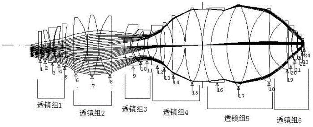
[0027] figure 1 It is a schematic diagram of the layout of the aspheric ultraviolet lithography objective lens of the present invention. 23 optical elements form transmission group 1, transmission group 2, transmission group 3, transmission group 4, transmission group 5, and transmission group 6, which are arranged sequentially from the beam incident direction.

[0028] The transmission group 1 is a transmission group with negative refractive power, including a first flat protective window 1 , a first positive lens 2 , a first negative lens 3 , a second positive lens 4 and a second negative lens 5 . The light projected from the object plane diverges through the transmission group 1 and then enters the transmission group 2.

[0029] The transmission group 2 is a ...


PUM

PropertyMeasurementUnit
transmittivityaaaaaaaaaa

Abstract

The invention provides an aspheric ultraviolet photoetching objective lens which is used for imaging an image of an object plane to an image plane. The aspheric ultraviolet photoetching objective lens comprises a transmission set 1, a transmission set 2, a transmission set 3, a transmission set 4, a transmission set 5 and a transmission set 6 in the optical axis direction, the transmission set 1, the transmission set 2, the transmission set 3, the transmission set 4, the transmission set 5 and the transmission set 6 are sequentially arranged in the incident light beam direction, the transmission set 1 has negative power, the transmission set 2 has positive power, the transmission set 3 has negative power, the transmission set 4 has positive power, the transmission set 5 has positive power, and the transmission set 6 has positive power. The aspheric ultraviolet photoetching objective lens has the advantages of being good in imaging quality, compact in structure, higher in photoetching efficiency and the like.

Description

technical field [0001] The invention relates to an aspherical ultraviolet lithography objective lens used in lithography technology and semiconductor element manufacturing device, belonging to the technical field of projection optics. Background technique [0002] Optical projection lithography is an optical exposure process that uses the principle of optical projection imaging to transfer high-resolution patterns to rubber-coated silicon wafers by step-and-repeat or step-and-scan exposure of IC patterns on the mask. Optical projection lithography is developed on the basis of contact and proximity lithography. The use of projection lithography can prolong the service life of the mask, and if the projection objective lens with reduced magnification is used, it is also convenient for mask production. Optical projection lithography has experienced the development of stepper and scanner. With the continuous advancement of science and technology, various types of semiconductor ...

Claims


Application Information

Patent Timeline
Patent Type & Authority Patents(China)
IPC IPC(8): G02B13/18G02B13/14G02B13/00G03F7/20
Inventor 白瑜邢廷文林妩媚朱红伟吕保斌邓超廖志远
Owner INST OF OPTICS & ELECTRONICS - CHINESE ACAD OF SCI
Why Eureka
Try Eureka