Outdoor switching device

A switchgear, open-air technology, applied in the direction of switches with movable transmission contacts, etc., can solve problems such as unreliable contact of contacts and unstable pivot arms

Inactive Publication Date: 2014-03-05
SIEMENS AG
View PDF6 Cites 0 Cited by
  • Summary
  • Abstract
  • Description
  • Claims
  • Application Information

AI Technical Summary

Problems solved by technology

If thinner elements are used to reduce mass, there is a risk that the pivot arm itself becomes unstable and the contacts only make unreliable contact

Method used


Image

  • Outdoor switching device
  • Outdoor switching device
  • Outdoor switching device

Examples


Embodiment Construction

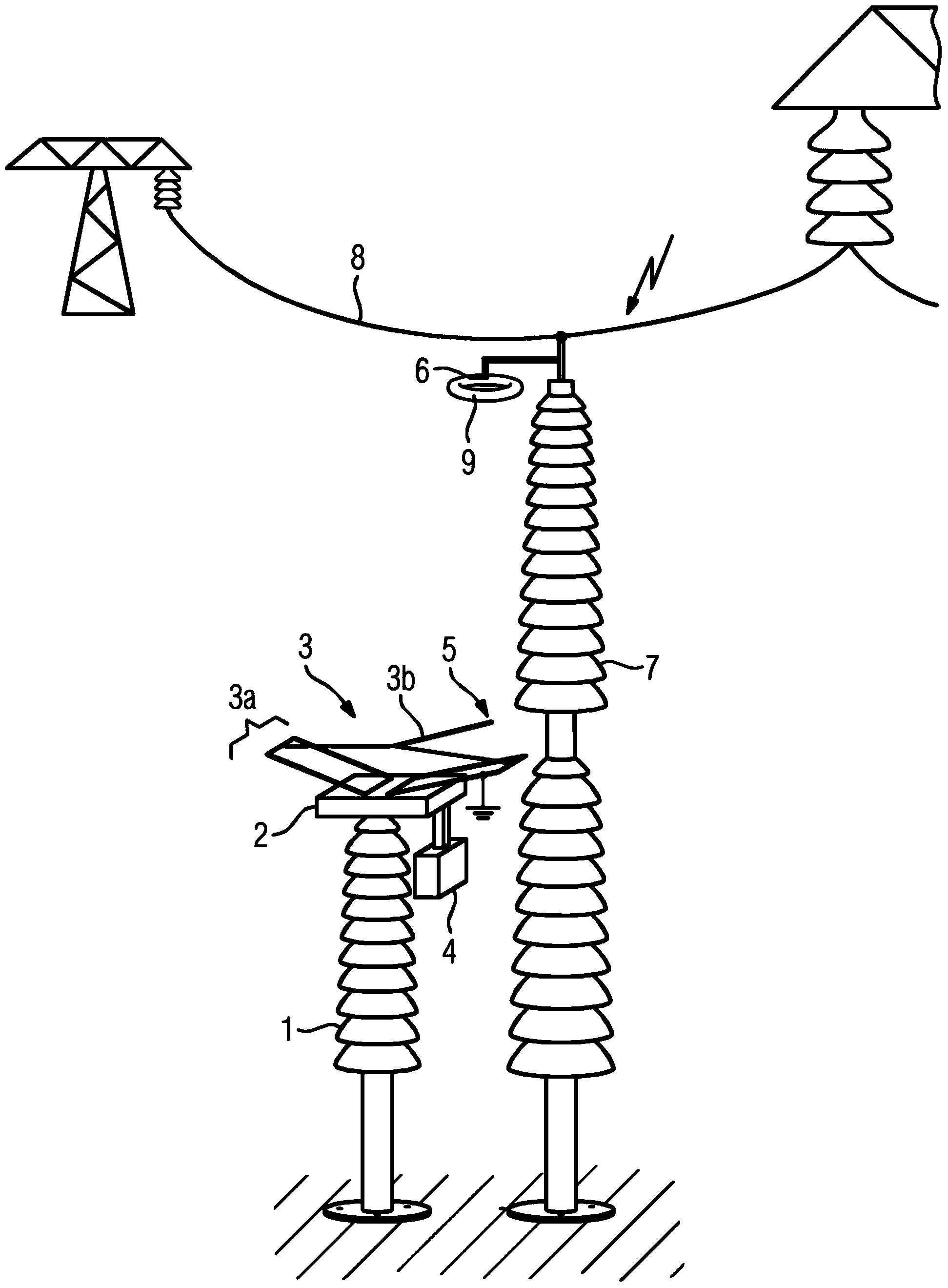
[0037] figure 1 is a perspective view of an open-air switchgear in the form of an earthing switchgear. The weather switchgear has a first support insulator 1 . The first support insulator 1 is shown here, for example, as a cylindrical first support insulator 1 , which is supported on a foundation. The longitudinal axis of the first support insulator 1 is oriented vertically. The first support insulator 1 is provided with a base plate 2 at its end protruding from the base. The base plate 2 is used for positioning the drive 3 . Furthermore, a drive box 4 is provided on the base plate 2 for actuating the drive device 3 . Devices for moving the drive are provided in the drive housing 4 . For example, an electric motor which converts electrical energy into a motion which is transmitted to the drive 3 can be located in the drive housing 4 . In addition, control and monitoring units, protective devices, locking devices, etc. can also be arranged in the drive box.

[0038] The ...


PUM


Abstract

An outdoor switching device has an outdoor switching path and a first contact piece (5) and a second contact piece (6). The first contact piece (5) is moveable relative to the second switching contact piece (6) by means of a drive arrangement (3). The first contact piece (5) is arranged on a pivoting arm (3b) of the drive arrangement (3). The pivoting arm (3b) is mounted on a hoist gear (3a).

Description

technical field [0001] The invention relates to an open-air switchgear with an open-air circuit breaker interval, which has a first contact piece and a second contact piece, wherein the first contact piece can move relative to the second contact piece by means of a driving device, and is arranged on a pivot of the driving device. on the swivel arm. Background technique [0002] Such an outdoor switchgear is known, for example, from a translation of the European patent document DE602005000144T2. The weather switchgear here is referred to as a pivotable earthing switch, which has a first contact piece and a second contact piece. The first contact is pivotable about a pivot fulcrum so that it is movable relative to the second contact. It is thus possible to form an open-air breaking interval between the two contact pieces. [0003] With known open-air switchgears, the pivot arm is formed by using two electrically conductive sub-elements that are oriented in alignment and fas...

Claims


Application Information

Patent Timeline
Patent Type & Authority Applications(China)
IPC IPC(8): H01H31/36
CPCH01H31/36
Inventor M.舍普纳
Owner SIEMENS AG
Why Eureka
Try Eureka