Method for using retainer, and retainer

A retainer and actuator technology, which is used in earth-moving drilling, drilling equipment, drill pipes, etc., can solve problems such as occupying space, and achieve the effects of increased weight, increased clamping force, and large torque arm

Active Publication Date: 2011-10-12
SANDVIK MINING & CONSTR OY
View PDF6 Cites 7 Cited by
  • Summary
  • Abstract
  • Description
  • Claims
  • Application Information

AI Technical Summary

Problems solved by technology

The disclosed structure takes up a lot of space on the feed beam

Method used


Image

  • Method for using retainer, and retainer
  • Method for using retainer, and retainer
  • Method for using retainer, and retainer

Examples


Embodiment Construction

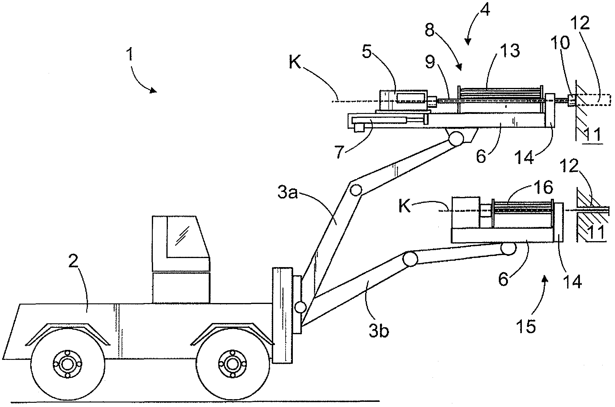
[0042] figure 1 An excavating device 1 is shown, which includes a movable vehicle 2 provided with one or more booms 3. The first boom 3a is a drilling boom provided with a rock drilling unit 4. The drilling unit 4 includes a rock drilling machine 5 which can be moved on a feed beam 6 by a feed device 7. The rock drilling machine 5 may be provided with a tool 8 coupled to it and comprising a plurality of consecutive drill rods 9 which are attached to each other by connecting means such as threaded joints. In addition, at the distal end of the drill rod, there is a drill bit 10 which has a drill button which is used to create a borehole 12 into the rock 11. The rock drilling machine 5 may include an impact device for delivering impact pulses to the tool 8 which transmits the impact pulse to the drill bit 10 and further to the rock 11 to be broken. The rock drilling machine 5 may also include a rotating device that allows the tool 8 to rotate about its longitudinal axis during d...


PUM


Abstract

The invention relates to a method for using a retainer, and to a retainer. The retainer(14) comprises a first clamping arm (18a) and a second clamping arm (18b) provided with clamping jaws (21a, 21b) for clamping a drill rod (9), a rock bolt or the like. The clamping arms are turned in relation to their pivot points (19a, 19b) by an actuator (20), whereby the clamping jaws move either towards or away from each other. On the portion between the pivot points of the clamping arms there are shape members that interconnect the movements of the clamping arms to make them interdependent and thus synchronize the movements of the clamping arms in both directions of movement of the clamping arms.

Description

Technical field [0001] The present invention relates to a method for moving the clamping arms belonging to the holder of the excavating equipment in such a way that the clamping claws provided in the clamping arms move toward each other at the same time, and the clamping claws The drill rod, rock bolt or similar excavating tool is clamped between, and the drill rod, rock bolt or similar excavating tool is located in the drilling center of the rock drilling unit or another excavating device. Mechanical synchronization is provided between the clamping arms so that their movements are interrelated. [0002] The invention also relates to a holder for the feed beam of a rock drilling unit, a rock bolt device or similar excavating equipment. The holder includes at least two clamping jaws moved by one or more actuators. There is a synchronization mechanism between the clamping arms so that their movements are interrelated. [0003] The field of the invention is described in more detail ...

Claims


Application Information

Patent Timeline
Patent Type & Authority Applications(China)
IPC IPC(8): E21B19/24E21B19/16
CPCE21B19/163E21B19/24
Inventor 尤哈·皮波宁萨米·凯雷宁
Owner SANDVIK MINING & CONSTR OY
Why Eureka
Try Eureka