Hydraulic coil upender

A rolling machine and hydraulic technology, applied in the field of rolling machines, can solve problems such as expensive maintenance costs, increased production costs, and damage to the turning plate, and achieve the effect of avoiding uneven force on the left and right

Inactive Publication Date: 2014-03-12
TIANJIN TIANZHONG ZHONGZHI TECH ENG CO LTD
View PDF9 Cites 6 Cited by
  • Summary
  • Abstract
  • Description
  • Claims
  • Application Information

AI Technical Summary

Problems solved by technology

[0003] The hydraulic coiler is generally used in the hot-rolled strip steel production line. Its main function is to turn the steel coil from the horizontal state to the vertical state to meet the requirements for the stacking and transportation of strip steel products. The structure of the hydraulic coiler commonly used in production is One end of the hydraulic cylinder and the rocker arm is hinged, the other end of the rocker arm is axially fixed to the rotating shaft through the key, the rotating shaft is axially fixed to the flap through the left key and the right key, and two bearing seats are set at both ends of the rotating shaft for Support the flap and the rotating shaft. Although such a structure can well achieve the purpose of turning the steel coil, because the flap is long, it is difficult to ensure the relative position when processing the keyway. Generally, the key on the side needs to be repaired to install it smoothly. Therefore, this assembly method can easily lead to different lateral clearances between the left button and the right button, and cannot guarantee that the left button and the right button can bear the load at the same time. In addition, because all the turning force of the turning hydraulic cylinder is transmitted to the flap through the left button and the right button, Therefore, the frequency of damage to the left and right keys is very high, and it is very time-consuming and laborious to replace the damaged keys, which seriously affects the normal production. What's more, the damage of the keys leads to the damage of the flap, and the maintenance cost is very expensive, which increases the production cost.

Method used


Image

  • Hydraulic coil upender
  • Hydraulic coil upender
  • Hydraulic coil upender

Examples


Embodiment Construction

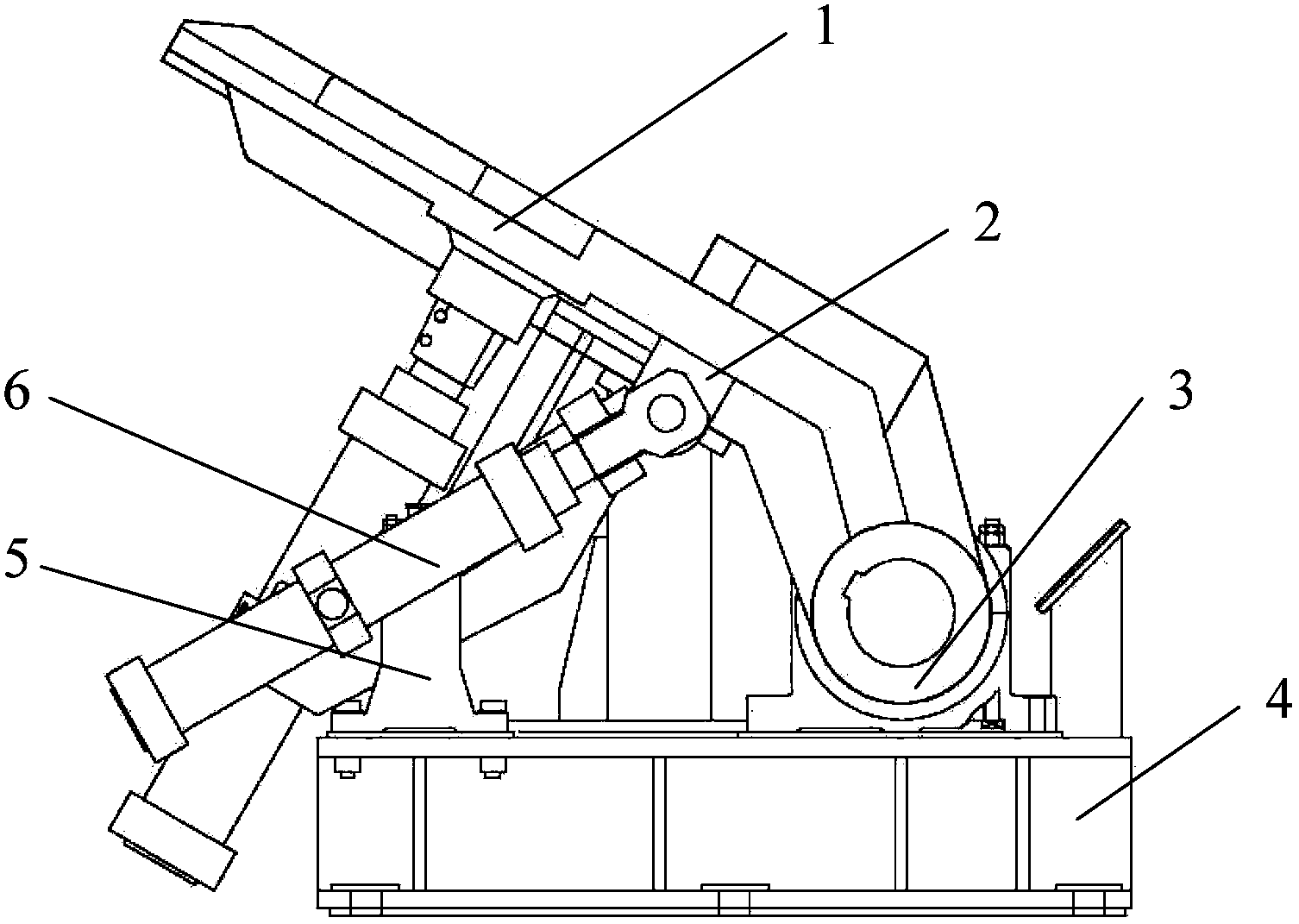
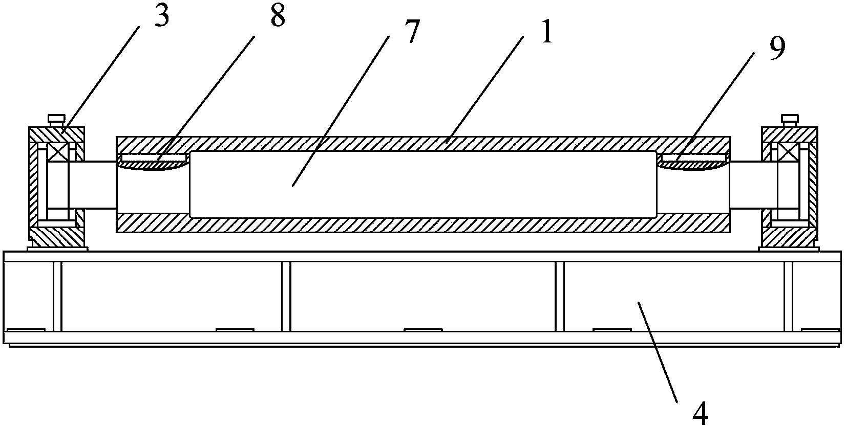
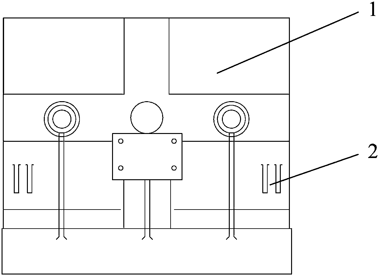
[0011] The following is attached Figure 1-3 The present invention is further described:

[0012] attached Figure 1-3 Middle: 1-flap, 2-hinge ear, 3-bearing seat, 4-base, 5-support seat, 6-hydraulic cylinder, 7-rotation shaft, 8-left button, 9-right button.

[0013] The present invention is provided with base 4, support seat 5, hydraulic cylinder 6, turnover plate 1, bearing seat 3, rotating shaft 7, left key 8, right key 9, support seat 5 and bearing seat 3 are arranged on base 4, bearing seat 3 It is arranged at both ends of the rotating shaft 7 and is hinged with the rotating shaft 7. The turning plate 1 is axially fixed with the rotating shaft 7 through the left key 8 and the right key 9. The lower bottom surface of the turning plate 1 is provided with hinge ears 2, and the hydraulic cylinder 6 is hinged The ear 2 is hinged with the flap 1, and the number of hydraulic cylinders 6 is 2 or more. In this embodiment, 2 are taken as an example. The number of hinged ears 2 is...


PUM


Abstract

The invention belongs to the field of steel rolling equipment, in particular to a hydraulic coil upender. The hydraulic coil upender comprises a base, a supporting base, a hydraulic cylinder, an overturning board, bearing pedestals, a rotary shaft, a left key and a right key, the supporting base and the bearing pedestals are arranged on the base, the bearing pedestals are arranged at the two ends of the rotary shaft and hinged to the rotary shaft, the overturning board is fixedly connected with the rotary shaft axially through the left key and the right key, hinged lugs are arranged at the lower bottom face of the overturning board, and the hydraulic cylinder is hinged to the overturning board through the hinged lugs; due to the fact that the hydraulic cylinder is directly hinged to the overturning board through the hinged lugs, the transmission path of overturning force is changed into directly force application to the overturning board through the hydraulic cylinder, and the problem that the left side and the right side of the rotary shaft are not stressed evenly due to a side gap formed when the left key and the right key are machined is solved.

Description

[0001] technical field [0002] The invention belongs to the field of steel rolling equipment, in particular to a coiler. Background technique [0003] The hydraulic coiler is generally used in the hot-rolled strip steel production line. Its main function is to turn the steel coil from the horizontal state to the vertical state to meet the requirements for the stacking and transportation of strip steel products. The structure of the hydraulic coiler commonly used in production is One end of the hydraulic cylinder and the rocker arm is hinged, the other end of the rocker arm is axially fixed to the rotating shaft through the key, the rotating shaft is axially fixed to the flap through the left key and the right key, and two bearing seats are set at both ends of the rotating shaft for Support the flap and the rotating shaft. Although such a structure can well achieve the purpose of turning the steel coil, because the flap is long, it is difficult to ensure the relative positio...

Claims


Application Information

Patent Timeline
Patent Type & Authority Applications(China)
IPC IPC(8): B21B39/20
Inventor 宋玉侠邵辉孙立国
Owner TIANJIN TIANZHONG ZHONGZHI TECH ENG CO LTD
Why Eureka
Try Eureka